Apparently, moving to lower levels does help for more qualitative evaluation, indeed! Absolute figures is another story. Nevertheless, it's a nice way to manually compensate for the ADC distortion.
Attachments


THD reading remains good because the interface's ADC THD lowers almost proportionally as a test signal level lowers. Down to a useful dynamic range point. Quantifying the DUT's THD performance alone is all well. For best THD+N (inverse of SINAD) you would prefer max or near max input test signal for the analogue to digital converter of course. Your second (-8.6dB) picture looks near sweet spot for both figures, also with a visually low interface THD spikes signature.
Ofcause.You still need to first test linear + amp in the chain vs switcher + amp in the chain. I wouldn't worry about anything else until that test is done and graphed.
Well i ran some test with my LM4780 Cloneamp.
The switcher (Lenovo USB charger) wins by as little difference as can be seen.
Pictures speak for themself 🙂
Test setup:
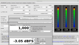
All setup's with Victors 1KHz at 1.055V
Shown here is with Cloneamp. loaded with 8ohm and sending out 1v
(I took at different voltages(0.5v, 0.75v, 1v and 2.8v - with simulair result's, e.g no difference with different's PSU)
I still need to test with the direct in mod @YashN, but i belive it will be alike, but let's see when i have it done.
(PC ---> Behringer)
(PC ---> SWITCHER+PSU/USB-splitter-box ---> Behringer)
(PC ---> LINEAR5.2vdc+PSU/USB-splitter-box ---> Behringer)
As last time, i also tested the same 3 setup's with the USB isolator attached in the chain. (PC ---> USBIsolator ---> PSU/USB-splitter-box ---> Behringer)
No difference when in use through.
EDIT :: Attached schm. of amp.
Attachments

Last edited:
Very cool, Jesper. They're all quite close it seems when using the differential mod. I expect the single-ended mod to show more interactions and more THD, so looking forward to it if you try.
To keep good measurements like these, you will want to document your tests but also mention how the amp itself is powered, and how power distribution is done among all three devices (PC, interface, DUT). This all has an incidence on what harmonics are produced, and the resulting harmonics will also depend on whether the DUT and other devices in the chain are isolated properly or not.
So, here, we know what you used to power the interface, but we do not know which solution powers the DUT: Linear Regulated, SMPS, or Battery.
We also do not know how the Power Distribution is among the three, for instance: all three on the same power bar or one or two on a different AC distribution outlet or other. This can have an incidence too - things like Ground loops and leakage currents - and I expect the differential mod could get rid of a portion of it (but not all and it's worth investigating).
And finally, and I think you must know this or have come across other people mentioning it in related threads around here: sometimes, just the presence of a lamp, especially those with dimmers or ballasts in the same power distribution, totally wrecks SQ (Sound Quality), and therefore will affect measurements in these cases too.
By documenting these, and avoiding the polluters, you should get great, repeatable, measurable results with the same configurations.
All in all, stellar progress, and you always manage to keep your work area clean. 😀
Last edited:
Maybe a year ago or so, I did some hacks on a synth during the day, improving the signal path. After some quite good audible results, I went to sleep late and decided to take up some more investigations the next night.
Next night arrives and I listen to the synth before attempting any further hacking. To my surprise, the sound is back to a very bland state instead of the lush, nicely overdriven sound of the past day.
After being puzzled by this for a while, I realised that since I had decided to work on it at night, I had installed a lamp (of course, with ballast) on the same AC outlet to illuminate the synth PCBs so that I can investigate further.
Great sounds returned as soon as I removed the lamp.
Yes.Jesper do you have a laptop available, as a way to avoid one connection to mains AC ?
All measurement is with laptop unplugged from mains.
Sometimes the switchers produce 100Hz + harmonics, so i avoid using them.
Except one of them which i used to test the setup (usb power, switcher power etc... to the soundcard)
I'am trying to find the source/cure of the 100Hz in my cheap cloneamp. I donno if snubbering will cure it? I can't seem to find good information regarding this.
Yesterday i ordered parts & pcb for building the Qasimodo test rig. Let's see if it can be useful or at least a good learning experience for me.
Thanks for the reply.
Jesper.
From post #426 it looks like Victor's generator is mains powered - is it possible to battery power that for enough time to do a comparison measurement? Otherwise it looks like there are no connections from any equipment connected to mains for a simple loopback?
Another test is to use the soundcard for signal generation, and not use Victor's generator, as a comparison change in powering setup.
I can suggest trying to use two large aluminium food trays (or similar) with all equipment (except laptop) sitting in one tray for a simple loopback, and the other tray acting as a full-shield metal cover over the bottom tray. That is one way of suppressing hum/noise from a bench setup. The other aspect is the quality of screening of interconnect cables, which should be as short and direct as practical.
Hi @trobbinsFrom post #426 it looks like Victor's generator is mains powered - is it possible to battery power that for enough time to do a comparison measurement? Otherwise it looks like there are no connections from any equipment connected to mains for a simple loopback?
Another test is to use the soundcard for signal generation, and not use Victor's generator, as a comparison change in powering setup.
I can suggest trying to use two large aluminium food trays (or similar) with all equipment (except laptop) sitting in one tray for a simple loopback, and the other tray acting as a full-shield metal cover over the bottom tray. That is one way of suppressing hum/noise from a bench setup. The other aspect is the quality of screening of interconnect cables, which should be as short and direct as practical.
I didn't have the time yet to try it out.
But i actually did some test before with some food-tray's - This was before i modded the Behringer with the balanced input; so it shall be interesting to see this.
Regarding the difference using Victor's on mainspower and the internal generator, it's only the THD number's which are worse using the internal.
I never tried Victor's with batterypower, which i shall see if i can try one of the day's (will have to collect some 9vdc's battery 4pcs.
Jesper.
My two cents... With the balanced input it's unlikely to have a ground loop between the DUT and the soundcard input. Moreover, it's proven when you had Victor's gen connected directly to the soundcard. And I think it's also unlikely the 100Hz to come from SMPS since these usually work at much higher frequencies. One thing you could try is to capture a FFT of your amp with its input not connected anywhere. Maybe it doesn't like a grounded source? Is the amp grounded to chassis?
Guy's...
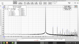
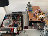
I did some more testing today.
* Trying to get rid of the 100Hz + friends.
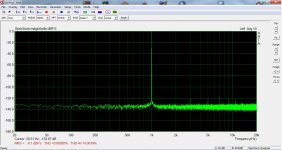
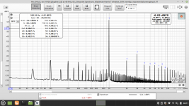
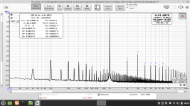
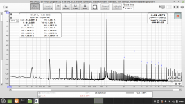
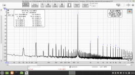
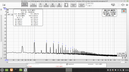
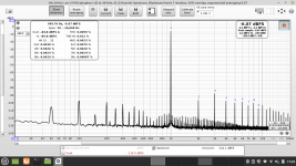
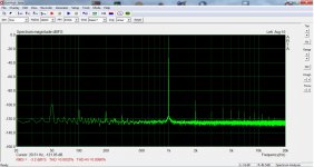
First my CloneAmp. with Victors, second with internal generator, then with my Amanero USB & a cheap Chinese DAC (Good enough i can see 😎)
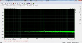
And Cloneamp. with no source connected (100Hz is there)
Pictures speak for themself.
Tried with GND comnection "lift", this was only resulting in higher 50Hz.
So i'am 99% sure that the 100Hz is comming from the Cloneamp. itself.
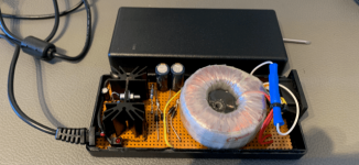
The Amanero + DAC is feed with one of DimDim's PSU he made for some RPI's.
This psu is also with both transformer & diodes + regulator ofcause.
@MagicBus, the psu for the Victor's is a homemade LM317 +35vdc with transformer & diodes inside.
@trobbins I did some "short" test's with aluminium tray's, but having none effect.
It's really surprising to see how good this little DAC is 🙂
Jesper.
I did some more testing today.
* Trying to get rid of the 100Hz + friends.
First my CloneAmp. with Victors, second with internal generator, then with my Amanero USB & a cheap Chinese DAC (Good enough i can see 😎)
And Cloneamp. with no source connected (100Hz is there)
Pictures speak for themself.
Tried with GND comnection "lift", this was only resulting in higher 50Hz.
So i'am 99% sure that the 100Hz is comming from the Cloneamp. itself.
The Amanero + DAC is feed with one of DimDim's PSU he made for some RPI's.
This psu is also with both transformer & diodes + regulator ofcause.
@MagicBus, the psu for the Victor's is a homemade LM317 +35vdc with transformer & diodes inside.
@trobbins I did some "short" test's with aluminium tray's, but having none effect.
It's really surprising to see how good this little DAC is 🙂
Jesper.
Attachments
-
 CloneAmp-Victors_Linear-reg-psu.png49.1 KB · Views: 126
 -
 CloneAmp-NO_source_connected.png44.2 KB · Views: 112
 -
 Cloneamp-internal-gen.png47.1 KB · Views: 130
 -
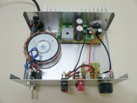
 TheClone.jpg507.9 KB · Views: 128
 -
 Amanero-DimDims-1A-psu.png42 KB · Views: 138
 -
 Cloneamp.-Amanero1000KHz.png46.9 KB · Views: 132
 -
 LM317-PSU.PNG102.7 KB · Views: 143
 -
 Really-good-little-nice-DAC-combo.jpg596.8 KB · Views: 143
 -
 Amanero-REW.png37.8 KB · Views: 148
Hey...
I just tried removing the transformer (which i also did last week, when changing the grounding of this amp.) 30cm. away from the chassis.
The 100Hz spike is excatly the same.
It's proberly just as it is? - Will think again, maybe i will eventuelly cure it ? 🙂
Right now, i have no clue... maybe tonight in Zzz... !
Jesper.
Second try... The ground star has four wires. One from front panel/pot body, one from rear panel, one from transformer center tap and one from underneath the pot -input ground(?) Try to lift the transformer center tap.
Nice!
Power solution for the Osc (Victor's here) should definitely be added to the documentation of a measuring session.
Additional fun stuff stemming from your tests rig above: you can now also investigate in detail how powering solutions and distribution work in a mixed system: Digital + Analogue, in particular, how easily in a build, the digital can wreck the analogue side in certain common configurations found even in commercial gear.
If you remember what I mentioned in a previous post too, there's a need to check within the audio chain the whole span of damaging effects (various PSUs, Distribution method), especially when AC Mains is involved. Some gear will just pollute it and may also additionally pollute signal paths.
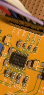
& a cheap Chinese DAC (Good enough i can see 😎)
It's really surprising to see how good this little DAC is 🙂
PCM5102 or something like that?
Hey.
The little DAC is for sure 5102... Your'e eyes are good @YashN 🙂
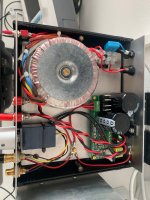
Yesterday, i took out the pcb, containing the clone, to measure if something was wrong with the diodes or like.
With my scope i could see, that everything was as it should be.
The diodes are MBR10100 Link! , and schottky and besides that it's not needed for the slow 50Hz, the voltagedrop on them are lower than normal 4007 one's.
I'am tempted to change them to normal diodes, eventhrough i know it proberly don't will change anything.
So regarding the star-gnd connection i did, i allready tried combination's of different wireing, i also tried disconnecting the psu CT from the gnd, with no change.
The changes in the 50Hz droppet to half, when i connected the frontplate + potmeter + backplate together. - There was never any change in the 100Hz spike.
On to thinking again! 🙂
Jesper.
The little DAC is for sure 5102... Your'e eyes are good @YashN 🙂
Yesterday, i took out the pcb, containing the clone, to measure if something was wrong with the diodes or like.
With my scope i could see, that everything was as it should be.
The diodes are MBR10100 Link! , and schottky and besides that it's not needed for the slow 50Hz, the voltagedrop on them are lower than normal 4007 one's.
I'am tempted to change them to normal diodes, eventhrough i know it proberly don't will change anything.
So regarding the star-gnd connection i did, i allready tried combination's of different wireing, i also tried disconnecting the psu CT from the gnd, with no change.
The changes in the 50Hz droppet to half, when i connected the frontplate + potmeter + backplate together. - There was never any change in the 100Hz spike.
On to thinking again! 🙂
Jesper.
Attachments
That's for the amp or for the interface? The interface definitely needs something to be done like this, otherwise it is not very well shielded.The changes in the 50Hz droppet to half, when i connected the frontplate + potmeter + backplate together. - There was never any change in the 100Hz spike.
I like Schottky's myself.
Jesper, your clone amp appears to use the same screw terminal for both the transformer secondary CT and the link to chassis ground - is that correct? Does the signal input ground itself at the input socket, or via the pcb to that power supply screw terminal ? The speaker outputs appear to be connected to ground through the pcb somehow. Is there a link to that pcb to show its trace outline?
- Home
- Design & Build
- Equipment & Tools
- Behringer UMC 202HD for measurements