lumanauw said:What input transformer to use? Where to buy?
Well, it has to be audio signal transformer familiar with these specifications:
- input impedance from 600ohm to 1kohm
- output impedance from 5kohm to 10kohm
- 1:10 primary to secondary windings ratio
- all around shielding (optional)
- audio-bandwidth linear frequency response
Searching the internet should produce some succes finding it.
Well, I am disappointed to realize that famous “bxcvb” was just a typo… through deciphering I almost found hidden connection with Book of Revelation and Da Vinci Code… Tra… Tra… 
I will follow this thread from a side, because I left my transformers in Jurassic Park! 😀
I will follow this thread from a side, because I left my transformers in Jurassic Park! 😀
boraomega said:I'll probably try this in the near future. 😎
Forget the transformers and keep going on with this one

Certainly! I kissed and left transformers for good more than 25 years ago…Lazy Cat said:Forget the transformers and keep going on with this one
OK 😉
Will you go on with the project at post #19, I would really like to see something working at the end? 😀
Will you go on with the project at post #19, I would really like to see something working at the end? 😀
@Lazy Cat: "I would really like to see something working at the end?"
I understand that you already have a working amp with such output stage because you responded that way in one of your posts?!
I will give my best to try that my proposal, but it would have to wait… my personal and professional obligations are seriously impeding my DIY activities and I still have 5...7 of my projects to prototype. If I am lucky, maybe some of my younger apprentices will give it a try?!
Who knows, maybe some member of this forum will decide to try it? I would like to know that, and if nothing else, I will spend time to design and offer PCB and a layout file here for that friend... of course, for FREE as it is always from me. 😀
Very generous from you, I agree completely.😉
Regarding my schematics proposals, don't misunderstand me, I would just like to attract attention of enthusiasts to start thinking about different kind of an amplifier schematics solutions etc. Some good fresh ideas are desired.

One more example in attached image. 😀
Regarding my schematics proposals, don't misunderstand me, I would just like to attract attention of enthusiasts to start thinking about different kind of an amplifier schematics solutions etc. Some good fresh ideas are desired.
One more example in attached image. 😀
An externally hosted image should be here but it was not working when we last tested it.
Very generous from you boraomega, I agree completely. 😀🙂
Regarding my schematics proposals, don't misunderstand me, I would just like to attract attention of enthusiasts to start thinking about different kind of an amplifier schematics solutions etc. Some good fresh ideas are desired.
One more example in attached file.
Regarding my schematics proposals, don't misunderstand me, I would just like to attract attention of enthusiasts to start thinking about different kind of an amplifier schematics solutions etc. Some good fresh ideas are desired.
One more example in attached file.
Hi lazy cat,
I am a newbie in electronic, but your schematic is very attractive!
I know this is solidstate forum but , instead of the transformer, is it possible employ a triode as a gain stage? 🙄
What is the electric requirements of the "power stage"?
perdone my elementars questions!
Cheers,
Paolo
I am a newbie in electronic, but your schematic is very attractive!
I know this is solidstate forum but , instead of the transformer, is it possible employ a triode as a gain stage? 🙄
What is the electric requirements of the "power stage"?
perdone my elementars questions!
Cheers,
Paolo
Ooops, what a huge image I posted.  OK, at least it's visible for everyone. 😀
Welcome inertial. I see that you are interested in upper schematics with transformer at input. The beauty of this one is its simplicity and reliability and that's the greatest quest in audio quality.
Of course you can use triode as a gain stage, I even recommend you to do so.
I have made one simple and very good sounding triode VAS with BIGBT output stage of which schematics will also be published soon.
You can change 12V accu in series with 22ohm resistor with galvanic insulated 100mA current source.
The power stage needs good linear power supply enabling +/- 50V and some silent 300VA transformer per each channel. 😉
OK, at least it's visible for everyone. 😀 Welcome inertial. I see that you are interested in upper schematics with transformer at input. The beauty of this one is its simplicity and reliability and that's the greatest quest in audio quality.
Of course you can use triode as a gain stage, I even recommend you to do so.
I have made one simple and very good sounding triode VAS with BIGBT output stage of which schematics will also be published soon.
You can change 12V accu in series with 22ohm resistor with galvanic insulated 100mA current source.
The power stage needs good linear power supply enabling +/- 50V and some silent 300VA transformer per each channel. 😉
Lazy Cat said:
I have made one simple and very good sounding triode VAS with BIGBT output stage of which schematics will also be published soon.
You can change 12V accu in series with 22ohm resistor with galvanic insulated 100mA current source.
The power stage needs good linear power supply enabling +/- 50V and some silent 300VA transformer per each channel. 😉
Thanks Lazy Cat 🙂 ,
I am ansious to see your Hybrid schematic!
To be honest, I'm more interested in triode driver than transformer.
Input Transformer Less 🙂
Perdone me I am very limited in electronic.
what is "12V accu" ?
I was referring to how much voltage swing is required (from the "power follower") , on wich load ( Khoms), and how much mA current is required from the triode voltage gain stage.
Thanks,
Paolo
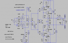
12V accu is a 12 Volt accumulator, storage battery, as you can see it in the middle of schematics. And for the reason it has to be charged somehow, it's maybe better to change it (together with series resistor 22ohm) with galvanic isolated 100mA current source. I can post that later on.
What is interesting in this schematics it is a diode bridge configuration for bias current enabling and at the same time signal blockade when 100mA current is not present (mute state). It is very ingenious solution and can be incorporated in between any VAS/OUTPUT stage you can imagine. Maybe you can explore in that direction.
Two 22kohm resistors in parallel are forming app. 11kohm VAS load to GND, so you can easily calculate current capability of VAS and its correct biasing. Required voltage swing is at least 55V if you would like to drive output stage to clipping.
Lazy Cat said:12V accu is a 12 Volt accumulator, storage battery, as you can see it in the middle of schematics. And for the reason it has to be charged somehow, it's maybe better to change it (together with series resistor 22ohm) with galvanic isolated 100mA current source. I can post that later on.
Thanks Lazy Cat, now I understand.
[
What is interesting in this schematics it is a diode bridge configuration for bias current enabling and at the same time signal blockade when 100mA current is not present (mute state). It is very ingenious solution and can be incorporated in between any VAS/OUTPUT stage you can imagine. Maybe you can explore in that direction.[/B]
I have seen diode bridge in italian schematic by Bartolomeo Aloia.
Very purist!
[
Two 22kohm resistors in parallel are forming app. 11kohm VAS load to GND, so you can easily calculate current capability of VAS and its correct biasing. Required voltage swing is at least 55V if you would like to drive output stage to clipping.
Only 11kohm load is hard life for symply little triode ( I like common cathode
) .What's happen if I swap those 2 resistor at double or quadruple values? Less bias current ? Perdone my rookie questions, I am searching to learn a bit " on the field" 😀
Finally, about 55V , do you mean 55V peak to peak ?
Very thanks,
Paolo
Originally posted by inertial
Only 11kohm load is hard life for symply little triode ( I like common cathode ) .
What's happen if I swap those 2 resistor at double or quadruple values? Less bias current ? Perdone my rookie questions, I am searching to learn a bit " on the field"
You may even leave out these 22kohm resistors it will still work, but with them you'll get better measurements results and of course better sound. The trick is that those two resistors have to serve both VAS (proper load) and output stage (input impedance) just right. You have to consider input capacitance of the output stage in parallel with these resistors and calculate the value accordingly to -3dB frequency turning point. Too high value or no resistors at all can not compensate capacitive influence of the MOS-FETs and whole output. Try to find just the right value that will not be too much to handle for your triode VAS but it certainly should be less than 50kohms (two 100kohm in parallel).
Finally, about 55V , do you mean 55V peak to peak ?
No, I meant 55V of half periode swing (positive, negative) that means 110Vpp. 😉
Modified Gecko
When I look at the schematic it does not show values for many of the resistors. This is a circuit that certinly looks intersting and I would like to build, could you share the component values with us?
Nico Ras said:Here is the original Le Gecko Plus output mods
When I look at the schematic it does not show values for many of the resistors. This is a circuit that certinly looks intersting and I would like to build, could you share the component values with us?
Hi MIKET
This design I like very much
We can all do the math and take it to play. 😀
This design I like very much
An externally hosted image should be here but it was not working when we last tested it.
We can all do the math and take it to play. 😀
Lazy Cat said:
You may even leave out these 22kohm resistors it will still work, but with them you'll get better measurements results and of course better sound. The trick is that those two resistors have to serve both VAS (proper load) and output stage (input impedance) just right. You have to consider input capacitance of the output stage in parallel with these resistors and calculate the value accordingly to -3dB frequency turning point. Too high value or no resistors at all can not compensate capacitive influence of the MOS-FETs and whole output. Try to find just the right value that will not be too much to handle for your triode VAS but it certainly should be less than 50kohms (two 100kohm in parallel).
Thanks , you are very kind
Excuse me , I need others info.
Vas: does it means voltage amplification stage?
How is approx the input capacitance of the output stage?
If I put two 100K in parallel ( or two 82K) the current bias go down, am I right? So more B class than A class, right?
No, I meant 55V of half periode swing (positive, negative) that means 110Vpp. 😉 [/QUOTE]
Thus 55: 1,414 = 38,9 V rms

Is this scheme near 180W/8ohm ?
Thanks for explanations 🙂
Cheers,
Paolo
Had to try the "compound-IGBTs" on a small Class-A hybrid Circlotron I have been working on. As I had no matched pairs Spice models I had to equalise current by adjusting R6 and R7.
The sims look quite good until clipping even though there is no NFB. THD is with H3 dominating. Extremely low anyway. Even going Class-AB without NFB looks quite impressing but of course with higher THD!
The sims look quite good until clipping even though there is no NFB. THD is with H3 dominating. Extremely low anyway. Even going Class-AB without NFB looks quite impressing but of course with higher THD!
Attachments
- Status
- Not open for further replies.
- Home
- Amplifiers
- Solid State
- Balanced IGBT for amplifier output