The answer to a question why people do what they usually do here is easily deduced from the avatar and/or sig line of a forum member. The discussions are mostly in service of it.
Huh? Don't just let it float out there, name them. Don't let that one flap in the wind.
The behaviour of the amplifier is crucial. No, this is about reproducing square waves to be listened to. As you say yourself, not a meaningful goal.
Hi Joe R,
I think that most of the LF driver producers are expecting that voltage (low output impedance) amplifier would be used, and so they are trying to make the drivers that would produce 'the best' response as possible under such conditions. Using a kind of EQ, I can imagine, can correct some smaller amount of driver 'imperfection' response. I think, that any kind of driver's response correction would produce almost the same voltage shape (amplitude) vs frequency while driver is producing the desired response. Only "a problem" is how to make as simple as possible solution to reach such goal (FR EQ, voltage or current feedback, voltage or current driver.....).
Regards
ivica
+1, just what I've been saying. Constant-current doesn't drive voice coils cleaner, just differently. But the end-result with drivers designed to be driven constant-voltage is not better. But constant-current corrected for inductance and error-back-EMF (by means of feedback loop) would be a great improvement (although needing EQ with presently designed drivers).Hi Joe R,
I think that most of the LF driver producers are expecting that voltage (low output impedance) amplifier would be used, and so they are trying to make the drivers that would produce 'the best' response as possible under such conditions. Using a kind of EQ, I can imagine, can correct some smaller amount of driver 'imperfection' response. I think, that any kind of driver's response correction would produce almost the same voltage shape (amplitude) vs frequency while driver is producing the desired response. Only "a problem" is how to make as simple as possible solution to reach such goal (FR EQ, voltage or current feedback, voltage or current driver.....).
Question: did esteemed tube amps of yesteryear like McIntosh and Stromberg-Carlson which had separate transformer feedback windings react to varying load impedance a bit like a constant-current amp?
B.
Last edited:
+1, just what I've been saying. Constant-current doesn't drive voice coils cleaner, just differently. .
But this is not what I am getting at, sorry. I am not promoting current drive.
But IF I was to use current drive, then your statement is not exactly accurate.
If the source impedance is many times that of the load, the back-EMF impedance largely disappears, and the current phase angle can NOT change under current drive. HUGE difference. Keep a look and focus on what the current does in the voice coil and then you will see that you have made an inaccurate statement.
Current drive: The current phase angle cannot change.
Voltage drive: The current phase angle WILL change.
Why will it change under voltage drive? Because the back-EMF impedance in series with the Re of the driver.
If there was no back-EMF in the driver - YOU WOULD BE RIGHT.
What you are surmising is an ideal situation where the V/I conversion will work perfectly. But the back-EMF impedance prevents that. This is why you statement is not correct.
BUT: Keep in mind that what I am talking about is the amplifier to produce constant current with respect to frequency, whether we are using a voltage source or current source, I am saying, EQ the current flat at all frequencies and the volatility of the back-EMF impedance is suppressed.
All the mechanical flaws of the driver/speaker shows up in the back-EMF impedance. Knowing that is a game changer. It makes the current reaching the Re part of the impedance less 'clean' to use your word.
So this is not about current drive. But it is about 'clean' current.
Cheers, Joe
Edit PS: Please also keep this in mind, if you EQ the current flat, you EQ the current phase angle flat too, the output impedance ability to influence goes away - now you have a loudspeaker that can both be voltage driven and current driven. Is that not neat?
Last edited:
I do not think current through the coils would change with the flat impedance the amp sees. Just the back EMF does on effect the amplifier so much.
how does one go about testing to see this?All the mechanical flaws of the driver/speaker shows up in the back-EMF impedance.
The problems are largely in the general mindset, as Joe also has often noted; and even partial current drive gives a great deal of the benefits. For LF tunings, there are solutions that work also with the established high-Qm drivers:gedlee said:That link sounds to me to be identical to Joe's claims - or maybe I just don't get it.
It is true that a constant current amp does lower some kinds of nonlinearity, but it creates a real problem with crossovers and LF tunings. One has to know what the impedance of the source is to design a good crossover. Hence constant current could be workable is the amp and speaker are sold together, but by the two as seperates is pretty much out of the question.
Introducing: Clean-Current Speaker with Transformer Aid and Closed-Channel Damping
I have to disagree. There is no such well-design method that would bring such dramatic distortion reduction as current-drive does. And there has really been very very little discussion on aspects of this principle, compared with how much journal pages or forum space has been filled up over the ages with any other, orders of magnitude less effective ways of tackling distortion in the reproduction chain.gedlee said:And then there is the age old problem of what distortion does one actually hear in a loudspeaker. If it is a well designed loudspeaker then it's not any that constant current will lower. So it seems to me that this is a lot of talk about something that is 1) hard to implement and 2) doesn't make a difference anyways.
That was a subwoofer, not very representative for evaluating current-drive.gedlee said:KEF made speakers with embedded constant current amps decades ago. It didn't go anywhere and was soon abandoned.
Weird judgment. Nobody has said current drive as a concept is something new. It is the flaws of voltage drive that had never been properly addressed and thus deserve every attention.gedlee said:So it's not new, just impractical and ineffective.
Makes for good copy though. One can always get a piece out of digging up this long dead horse.
Hold your horses! Here an Australian manufacturer that has recently adopted current-drive:
SGR Audio Releases CX4F Mk2 Loudspeakers | StereoNET Australia
The renowned monitor designer Bruno Putzeys has already long employed current drive, at least in the midrange, though he doesn't highlight it:
Kii Audio Three |
I also know a soundbar maker that has been considering an overall move to current amplification.
The awareness is rising, and there may be any number of powered speaker makers that are secretly exploiting the principles, though may yet find it difficult to publicly deviate from the damping factor narrative.
how does one go about testing to see this?
For a start, the Re part of the impedance is immune. The other way is single using a driver as a crude microphone. Speak into it and you know what you get is a voltage appearing across the driver terminals. And so does every mechanical flaw of the driver, for a start, no cone is totally free of resonances, so not hard to see if any of these are triggered, and you can bank your house it will, this will also show up a voltage. The driver has a dual nature and it is the amp that gets the brunt, we know that the amp has no control over its current.
There is an awful lot going on, but the bottom line is that the current gets corrupted and there is still a reluctance to bite the bullet, that only the current through the voice coil creates sound, whatever voltage that appears is only incidental.
The sound that comes from your speaker was created by current, not voltage.
I have developed a different approach to that of Esa (ETM), but we have something in common, it is the current that matters!!!
Joe, I find all this very interresting. Can you tell me why you dont want to go for 100% current drive, instead of the way you describe? I am looking forward to read your paper about this if you go public, with It some time.
ok i have heard of something like this before but the term coined for it was called "flyback" voltage, but that was meant to describe (mis)behavior caused by reaching mechanical limits (without damage occurring) where the restoring force of the surround and spider are pulling the coil back (reverse polarity voltage is produced, as in the speaker acts like a microphone ) but what your describing seems quite different and happens before mechanical limits are reached, no?
when it comes to using a speaker as a mic i've done that for kick drum mic'ing before.
when it comes to using a speaker as a mic i've done that for kick drum mic'ing before.
Last edited:
...but what your describing seems quite different and happens before mechanical limits are reached, no?
when it comes to using a speaker as a mic i've done that for kick drum mic'ing before.
Yes, I am talking about something that happens all the time and your kick drum example shows that exactly.
Now imagine what your 'mic' is doing to the amplifier, not its voltage, but what it is doing to the current of the amplifier (I am talking about the amp being a voltage source). I will tell you what will happen, the the voltage source (which is represented by the back-EMF impedance of the speaker) will oppose and modulate the current that finally ends up flowing through the voice. This will modify what you hear, because what you hear is the current of the amplifier, and many are yet to grasp that. The voltage tells what should happen, but look at the current and that is what you end up hearing.
So when it is s 'mic' the speaker is a voltage source, but when you receive current from the amplifier, our 'mic' is now a speaker. What happens is not pretty.
Esa's (ETM) solution is current drive, and that does indeed stop the above from happening, I have no argument on that. Under current drive, the output impedance is very high and if many times the impedance of the driver, and that means many times the back-EMF impedance of the driver as well, then that will produce a voltage (which tricks some people up, because they will focus on that), but in fact what really happens is the the back-EMF impedance looses it ability to impede, so if 1 Amp under current drive, the Re part of the impedance will receive the full 1 Amp of current. Also the current phase angle will be zero, hence the ability of the speaker to produce (or rather draw) reacting current disappears. But with a voltage source amp, the back-EMF impedance has almost full reign (only limited by the Re, being the DC resistance of the voice coil) and now the current will change, the current phase angle will also change (but limited by Re).
Let us say that R = 6R and at 3KHz the total impedance is 18R. Now we subtract one from the other, and the back-EMF impedance at that frequency is 12R. Now how much current will reach and flow through the Re part of the impedance? Not hard to figure out that it will not be the full 1 Amp, it will be 1/3rd of an Amp. Also, the current phase angle will not be zero degrees. The speaker reacts to that modified current, but once in motion, the amplifier is now reacting cycle by cycle and you have a vicious cycle - one that will only get reduced by the music, the content dying. The dynamics come up again and the cycling renews. All because the back-EMF impedance is not stable, reacting constantly and modifying the current of the amplifier - and what the amplifier does current wise, that is what we end up listening to.
My idea is different from Esa's and comes down to making it difficult for the amplifier to produce reactive current. EQ the current, so that the amplifier produces the same current at ALL frequencies, the current phase angle of the amplifier will go near zero. It now becomes near impossible for the amplifier to produce reactive current. It does not eliminate the back-EMF impedance, but it short-circuits the ability of the back-EMF impedance making the current chase it own tail.
There is some added bonuses in using current EQ, and they are major:
1. The output impedance becomes largely cancelled out.
2. The LF tuning, as Earl calls it, the box alignment will always stay in place.
3. The crossover will also be immune - both the box and crossover no longer needs to see a zero Ohm source impedance.
4. You will end up with a speaker that can be both voltage driven and current driven.
These are not to be scoffed at. When I demonstrated the above to serious loudspeaker designer, you can see their eyes opening up. One day we will have commercial designs that will feature this. Many existing commercial designs, not all, can be converted. The EQ components must be seen directly by the amplifier terminals, so it can be external to the speaker. But best performance can be had by designing this from scratch and sound wise will pay of the best. Please, trust me on this, about a dozen designs and you end up with a speaker that does not sound average fare.
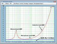
Please see attachment, where Re and back-EMF impedance is shown as part of the complete impedance plot of a driver.
Cheers, Joe
Attachments
Joe, I find all this very interresting. Can you tell me why you dont want to go for 100% current drive, instead of the way you describe? I am looking forward to read your paper about this if you go public, with It some time.
Because I believe that current drive might be the 'correct' drive, but there are numerous problems to put it into practice. But I believe there is a better and more practical solution and one that is compatible with both voltage and current drive - EQ the current and you can use both. This is not theory, this has been done, I even built an transconductance amplifier to prove it works.
"Trans-Amp" - 40 Watt Transconductance "Current Amplifier"
this makes perfect sense to me.
with respect to the question i asked earlier about two speakers in parallel doesn't that reduce the Re(resistance) that a voltage drive amp see's?
case in point two subs (should be a lot of back emf there, no!) paralleled, compared to the same two subs driven by separate amps. wouldn't preventing back EMF be a benefit there or is it harder to do at low frequencies?
i guess i'm looking for a system approach to the problem where multiple loads(speakers)may be grouped to be driven.
Last edited:
this makes perfect sense to me.
with respect to the question i asked earlier about two speakers in parallel doesn't that reduce the Re(resistance) that a voltage drive amp see's?
Yes, you halve the Re, but also the back-EMF impedance. In other words, there is no gain in just paralleling.
case in point two subs (should be a lot of back emf there, no!) paralleled, compared to the same two subs driven by separate amps. wouldn't preventing back EMF be a benefit there or is it harder to do at low frequencies?
Note the attachment I just posted in the previously in post #15034 and you will see that there are three different types of back-EMF that shows up in the impedance plot. Anything that plots above the Re value is the back-EMF impedance.
You will notice that some just talk about back-EMF (or reactive current attributed to it), but you will note that I use the phrase back-EMF impedance. This is very deliberate because it has an Ohm value and it actually shows up in the impedance plot. It seems the obvious is not always as obvious as you might think.
i guess i'm looking for a system approach to the problem where multiple loads(speakers)may be grouped to be driven.
Oh dear, that is a monster subject, because we have to understand what happens with the single driver first, then we can see that EQ the current is desirable. Then we have to put something between the amplifier and speaker units called a crossover. Things now gets even more complicated.
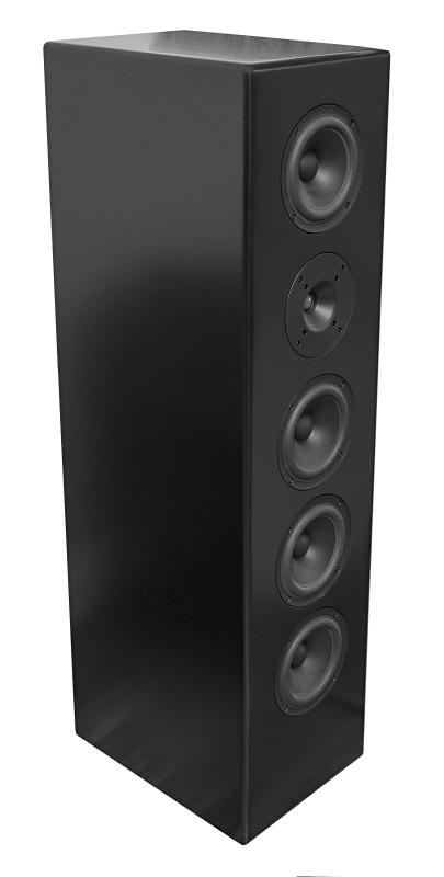
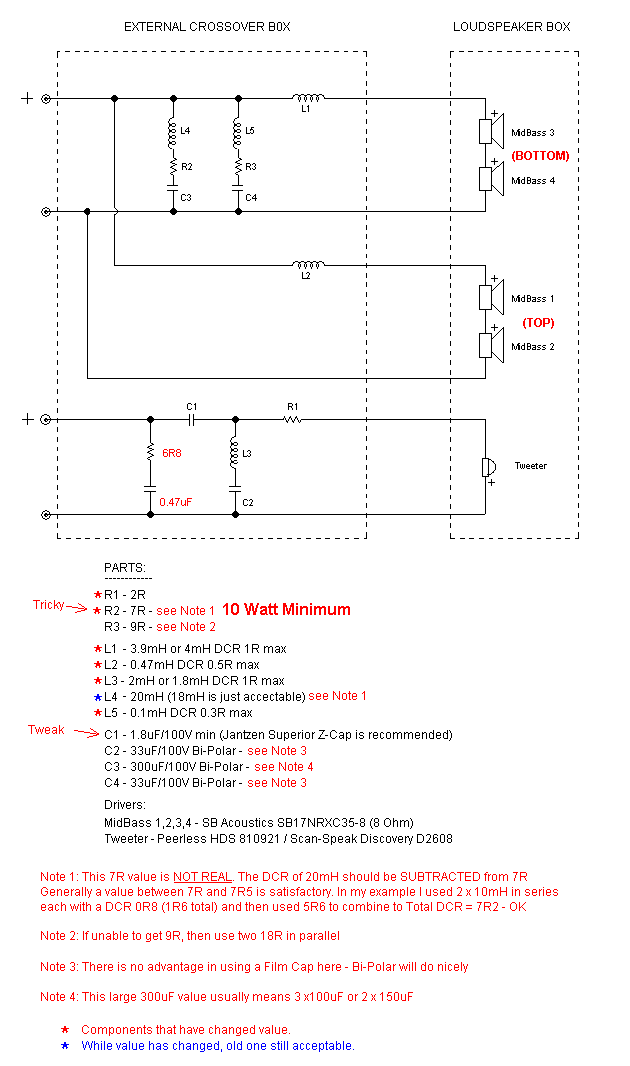
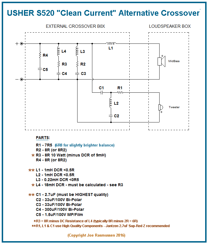
It would be way beyond explaining here, but I have developed a crossover methodology that does just that. You can see two examples online, the DIY Elsinore Project Speaker, now Mk6 -and the other is a rebuilt Usher S520 commercial speakers, where I just took out the crossover and put in a different one. This was a critical try because the drivers here were anything but ideal, they are cheap and not too nasty, so could it be made to work? It turned out it worked out OK.
Link: Elsinore Project Speaker Mk6


(Please note that the "+" and "-" legs must be put together, bi-amping is not to be done.)
Link: Elsinore Speakers DIY
Link: Usher s520 Crossover

Study the two crossovers because they have been designed in mind to minimise the back-EMF impedance from corrupting the current of the amplifier.
The basic principle is to put as much external series impedance to the driver, so the series inductor to be as large as possible and the series capacitor to the tweeter as low as possible value (note to Earl, Gedlee), here I use a tweeter waveguide to get the capacitor value down to near a third so the the reactance of the series capacitor is tripled).
The high pass to the tweeter is the real trick, note the LC there? The effect of it is to vary its Q as a null, so that it goes gradually from 1st order to 5-6 order. Varying that Q has major effect on flattening out the response just below the crossover frequency, while still maintaining good power handling.
Now please, understand that the above is just the tip of the iceberg, putting something complex into just a few words.
Cheers, Joe
Last edited:
guess i need time to go through this better.
i was thinking multiple drivers at a low impedance would make for more back EMF impedance.
i was thinking multiple drivers at a low impedance would make for more back EMF impedance.
perhaps a moderator needs to take all of this OCD current/voltage stuff & put it into a new thread - OCD: current/voltage. see if it can set a new record for # of pages. it should!
Yes, it should be separated off, however, it will get ignored - just like it should. This is all nothing but "the Emperor's new clothes." There is nothing there. If there was, then how has it been missed by ALL of the experts for decades and decades.
funny you should mention experts ignoring it.... from the article https://www.edn.com/design/consumer...periority-of-current-drive-over-voltage-drive
'There cannot be found any scientifically valid reasons that justify the adoption of voltage as the control quantity - it is only due to the historical legacy originated almost a century ago, most likely by cheapness and simplicity; the quality and physical soundness of operation have not been considerations in this choice. Engineers are also more accustomed to identifying electrical signals as voltages rather than currents."
when it comes to audio truth there are no experts...
Yes, it should be separated off, however, it will get ignored - just like it should. This is all nothing but "the Emperor's new clothes." There is nothing there. If there was, then how has it been missed by ALL of the experts for decades and decades.
While I agree this topic should be in it's own thread, I think its disingenuous proclaiming this is as "nothing" just cause others (or you) haven't looked into this thoroughly or feel its not worth the time. There's too many unknowns in this field the I would think everyone would encourage exploration. You may be right but there's too many angles for you or anyone else to thoroughly try, research and test all of them. I may be in the minority but I rather like reading different angles no matter how left field it may be
I think its disingenuous proclaiming this is as "nothing" just cause others (or you) haven't looked into this thoroughly
Excuse me, but that simply isn't true. Just because something sounds interesting doesn't make it factual. The analysis being given simply does not hold up to scientific rigor. It's all a smoke screen for something that has always been there, has always been understood and simpy is not a mystery. For example: calling an inductive impedance a "back EMF" is simply symantec. Would we call a capacitors impedance a "forward EMF".
- Status
- Not open for further replies.
- Home
- Amplifiers
- Solid State
- Back-EMF and flat impedance
