Hi Ivica
That link sounds to me to be identical to Joe's claims - or maybe I just don't get it.
It is true that a constant current amp does lower some kinds of nonlinearity, but it creates a real problem with crossovers and LF tunings....
Not identical at all.
As I just stated to Ivica, I am not into current driving. Whenever I open my big fat mouth, everybody wants to put me into that camp. Not so!
The approach I have is totally different and it does address the crossover and LF tuning problems, that is the whole point.
Think about for a second, or perhaps a little longer, if you make the amplifier produce the same current at all frequencies, even at the LF tuning (the box alignment), then it does not need a zero Ohm source impedance. Trust me, this works. I have done a dozen times now with different designs. The same goes for the crossover, it too no longer needs a zero Ohm source impedance, it gets locked in. Just make the amplifier produce the same current at all audio frequencies and that is how it works. Think it through and you will see why that is true. It's also quite fascinating.
Cheers, Joe
I am not a proponent of current drive ...
I am in favour of putting the voltage amp into 'constant current' mode ...
😕
I am not into current driving ...
... if you make the amplifier produce the same current at all frequencies ...
Isn't your last statement the very definition of a "constant current source"?
😕
Isn't your last statement the very definition of a "constant current source"?
Basically, you can look at what the MyRef project is doing. You are driving current, but you also use voltage feedback.
That is not exactly what the MyRef is doing, but it does have a current pump drive. With voltage feedback, you still have the response of a voltage amplifier. But you can control how the current drives. Yes, the current gain can be adjusted, and you can optimize it to different loads, but basically it will work with speakers like a voltage amplifier would do.
Thanks Joe, it's been a hard time pinning this down but see if I understand. Speakers receive constant Voltage, the amp supplies constant current and the conjugate splits the difference?
The effect is that the amp has a resistive load to work into, yes?
I'm not sure how you would do this and supply the speakers themselves constant current at the same time (unless you use buffered EQ, maybe?)
The effect is that the amp has a resistive load to work into, yes?
I'm not sure how you would do this and supply the speakers themselves constant current at the same time (unless you use buffered EQ, maybe?)
🙄 Creating a classic "constant current amplifier"!
Earl if you look at Joe's web site you will see an example of what I think he is talking about. Crossover, plus drivers showing a pure real impedance at the terminals (except at the lowest resonance). I have no problem with this, it's just the confusing way of explaining it. Saying it "forces" the amplifier into constant current mode is stating the obvious and leads to confusion. To add to the confusion are the comments about crossover distortion as if it is not a problem at zero degrees of phase between voltage and current.
I would defer to you if this has special merit with respect to speakers.
I'm not sure how you would do this and supply the speakers themselves constant current at the same time
Not likely, think about it.
Last edited:
II hear you and get that, but I still maintain that we tend to think voltage and not get the complete picture. Thinking voltage is an easy language, I find that current it not. Try explain current drive to the average guy, it is so counter-intuitive. I am not a proposing current drive though. Some get me confused about that. I use amplifiers that have typically 5 Ohm output impedance, because I make my own.
Take a manufacturers driver, where you have two versions, 4 Ohm and 8 Ohm. I am thinking of an actual 6" driver from a premium source. The voltage sensitivity is 89dB for 8 Ohm and 92dB for 4 Ohm. The voltage is the same, 2.83V RMS. The extra 3dB is entirely down to current, not voltage. Change current by 2:1 and it will be 3dB.
F=Bli where F is the final dB-SPL product.
I have tested this over and over again, the dB-SPL of the driver is always proportional to current and never the voltage. The above example proves it because the voltage did not change, only the current. I can give numerous examples where I have physically tested this as well as in SoundEasy modelling.
And isn't that what we ought to expect, when drivers are current devices. Yes, there is voltage there and yes, you need to have both to see the complete picture, such as calculating dissipated power.
Also, I put this fundamental thought to a physicist with a track record in he loudspeaker industry (I could name drop here) and quite in depth, more than I could cover here. One of the ideas is the back-EMF of the driver is an impedance since it impedes current. An impedance is always about the current and so is the impedance plot. Since back-EMF (motional, inductive, microphonic) impedes current, it is an impedance. And it can be measured at any frequency, the top of the impedance minus Re is the back-EMF impedance at that frequency in Ohm. It is a voltage source opposing and modifying the current of the amplifier. Only Re limits the back-EMF, which is just as well. The amplifier has no control over the current. It can only control the voltage.The voltage across Re times the current (less and impeded by he back-EMF impedance) is what gets dissipated in the voice coil and less that 1% gets converted to F or dB-SPL. The numbers that has come up supports this. The voltage across the Re part of the impedance is not the same voltage as that of the voltage source, the amplifier.
One thing is interesting though, if you EQ the current, so that the amplifier supplies the same current at all frequencies, then you have effectively cancelled out the output impedance of the amplifier. It is still there, but there will be no deviation in FR. This can be done to near perfection with sealed boxes and more difficult with vented boxes. It also makes the crossover not need to see a zero source impedance, so both box alignment and crossover behaves the same.
So that is incredibly practical too. Especially with the kind of amplifiers I do, 5 Ohm typically. The box alignment does not need to see zero Ohm.
Whew! That was more than I intended to type...
since you are talking about an amplifier with a 5 ohm output impedance, a couple of questions arise: 1) does this amp have an output autoformer?; 2) aren't you really talking about amplifier damping factor?😕
😕
Isn't your last statement the very definition of a "constant current source"?
Yes, I see.
Indeed I can see how it can be taken that way, but I was making reference to a voltage source, not a current source. So I must be speaking about something different from what Esa's book is about.
I did say "make the amplifier produce the same current at all frequencies" if you do that, then you can use both voltage and current source amplifiers. And Steve System7 said earlier here, he referred to a flat impedance, so we are clearly speaking about the load on the amplifier. The voltage source can only 'regulate' the voltage, it has no control the current at all. So we impose control.
But if the load impedance is made totally flat, as close to that of a resistor, then we have constant current with respect to frequency. Several interesting things happen, for one you can indeed use a current amplifier, if you wish. This is because the output impedance largely becomes cancelled out. Two, the LF tuning and crossover no longer needs to see a zero Zo from the amplifier. For example, a sealed box Butterworth Q=0.707 will stay that way, no matter what. Normally any added series impedance would blow out the alignment. Same goes for the crossover.
This isn't just theory, it is quite achievable and added complexity is over estimated. I have done a 2-Way system with 13 crossover parts. Actually, 8 was used for the current EQ (seen directly by the amplifier terminals) and he rest as the actual filtering. See attachments.
Mind you, at a deeper level, this is really about whether there is an additional and indeed audible reason to go down this way? Or is it just an academic exercise? Or does it give similar improvements to the sound in the way that proponents of current drive claims, but with non of the down sides? Can we get the same benefits that they claim, but from voltage drive?
I believe yes, even if it is not perfect, the compromises you have to make to get real current drive possible, makes it clear that there is no such thing as pure current drive anyway. Not in this world.
I believe that the improvement we hear, both constant current (voltage) and current drive, are due to nonstaining and restraining what the back-EMF impedance does on the current level, not voltage. Not in a perfect way, but suppressing that back-EMF impedance. Have given a lot of thought to this - but want to have respectful discussions about it.
That flat impedance, making the current the same at all frequencies, the real pay-off is that the current phase angle goes flat, virtually zero degrees. An amplifier cannot produce reactive current under those circumstances. In fact, the current load is resistive. So just as current drive is about the current, this proposed alternative is also about the current. And the one thing that corrupts current in unpredictable ways is the back-EMF impedance of the driver. Suppress it is the key to both. In fact that is the raison detre.
Cheers, Joe
Attachments

Your perspicuity knoweth no bounds.
Come to think of it, this load may explain a lot..
Can you clarify this please. EMF is a potential. Are you referring to the load that it sees or something else?back-EMF impedance
Come to think of it, this load may explain a lot..
Hmm, so maybe one amp will benefit more than another?An amplifier cannot produce reactive current under those circumstances.
Joe
i've a question with respect to back EMF
if i have an amp with an 8 ohm load and i reduce the load to 4 ohms (i.e. two speakers) does this open the door for more "back emf"?
i've a question with respect to back EMF
if i have an amp with an 8 ohm load and i reduce the load to 4 ohms (i.e. two speakers) does this open the door for more "back emf"?
This is backwards. Let's turn the discussion back on it's feet.
"Constant current" is a viewpoint that properly recognizes how to feed a Rice-Kellogg driver so as to have theoretically correct cone motions. It's also "damping by other means". Unfortunately - and rarely recognized - today's Rice-Kellogg drivers are artfully massaged into reasonably acceptable output assuming constant voltage driver signals.
In practice and in the absence of having the driver within a feedback loop, the only difference between voltage and current drive is in the EQ, with constant voltage drive not needing as much EQ with today's drivers in order to artfully fine-tune the sound at your ears.
A better way to advance this discussion is by asking how to get this cone motion (or in a perfect world, the sound at your ear) into the feedback loop. Before feedback by means of inexpensive accelerometers became the rage, feedback sensing relied on sensing the drive signal. The drive signal is bent-about by back-EMF and back-EMF also reflects error-back-EMF arising from erroneous motions of the cone (such as harmonic distortion of the suspension and more dramatically for our aural enjoyment, under-shoot and over-shoot on transients).
So it isn't meaningful to talk about current or voltage drive. An amp in a system with the driver VC in the loop will act as it needs to act to stabilize the feedback loop. The reference sensor in the feedback loop is based on sensing something which happens to be sort of characteristic of the viewpoint of the "constant current" advocates. This sensing can be done with a current-sensing series resistor or better in a Wheatstone Bridge which allows you to introduce partial compensation for the coil inductance (as constant current advocates and sim modellers are always complaining about) and other troublesome Rice-Kellogg idiosyncrasies.
B.
Last edited:
I did say "make the amplifier produce the same current at all frequencies" if you do that, then you can use both voltage and current source amplifiers.
I see what you are saying now.
You place a conjugate network across the speaker making it look like a flat real resistance across the band, this is rather well known. If the amp is a voltage source then this will have absolutely no effect on the speaker itself, although it could affect the way the amp works. Amps are not my expertise, but it is my understanding that as long as the loads reactive impedance is not too great the amp will work just fine.
However, if the amp does have a significant output impedance, then the the effect of this impedance on the speaker frequency response will still be seen by the speaker - this impedance is in series with the speaker. So I don't think that you comment above is correct. Unless "make the amplifier produce the same current at all frequencies" means adjusting the conjugate network taking the output impedance of the amp into consideration. But that then requires a different network for every amp that is not a pure voltage source. And if it is a well designed pure voltage source then all of this won't do anything of significance.
Last edited:
Right, without motional feedback, the only difference in driver behaviour between voltage and current is a slightly different signal which results in a slightly different sound output. Neither results in a particularly correct sound because that is determined by the shape of the driver and just a matter of what EQ to add. With today's drivers, the constant voltage will produce nicer anechoic plots because that's how the drivers are artfully crafted.
B.
B.
Beyond the Ariel
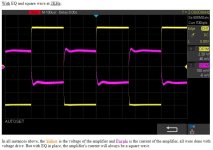
I have been preaching that for years. This does not necessarily mean you get a square wave at the output of the driver. It does reduce reactive feedback into the amp.
Also, if we look at voltage vs current passing through the driver itself, you still get the same voltage/current phase shift regardless whether you have that parallel network or not.
I see what you are saying now.
You place a conjugate network across the speaker making it look like a flat real resistance across the band, this is rather well known. If the amp is a voltage source then this will have absolutely no effect on the speaker itself, although it could affect the way the amp works. Amps are not my expertise, but it is my understanding that as long as the loads reactive impedance is not too great the amp will work just fine.
However, if the amp does have a significant output impedance, then the the effect of this impedance on the speaker frequency response will still be seen by the speaker - this impedance is in series with the speaker. So I don't think that you comment above is correct. Unless "make the amplifier produce the same current at all frequencies" means adjusting the conjugate network taking the output impedance of the amp into consideration. But that then requires a different network for every amp that is not a pure voltage source. And if it is a well designed pure voltage source then all of this won't do anything of significance.
I have been preaching that for years. This does not necessarily mean you get a square wave at the output of the driver. It does reduce reactive feedback into the amp.
Also, if we look at voltage vs current passing through the driver itself, you still get the same voltage/current phase shift regardless whether you have that parallel network or not.
Last edited:
I have been preaching that for years. This does not necessarily mean you get a square wave at the output of the driver. It does reduce reactive feedback into the amp.
Fussing about what load the amp sees is hardly a priority.
Likewise, it is possible to make "realistic" square wave sounds to the listener's ear and while full-range ESL enthusiasts might like showing off their close-mic square wave, not ordinarily a meaningful goal of driver design.
B.
I know this is difficult to do on social media, especially on a subject where we see people get bogged down into all kinds of minutia, a bit like not seeing the forest because of all the trees.
So over the years I have tried not to get side-tracked all over the place and actually focus on what matters. The topic of back-EMF is also all over that place. But the F in EMF stands for Force and that means it is a voltage generator that opposes the current of the amplifier (we are talking in terms of a voltage source - the back-EMF impedance under current drive cannot impede current). The thing that moderates the back-EMF is the DC resistance of the voice coil, the Re.
Once that was realised, a number of things emerged, one is that the back-EMF impedes current getting to the Re part of the impedance. It is in fact an impedance in series with Re. So if we have Re = 6R and at 3400 Hertz the total impedance is 18 Ohm (I am describing a real driver that I measured), then the back-EMF impedance is 12 Ohm. Only 33.333% of the voltage of the amplifier ends up appearing across Re. Indeed also, only 1/3rd of the current will flow through Re. It then dawned on me, and I did both physical measurements and used modelling to prove this, that the back-EMF is a voltage generator, it is an impedance, not a resistance. The Re is both and because it is a resistance, it also dissipates heat. Hence in simple terms, what happens across the Re part of the impedance is the actual engine room (maybe not the best description, but where the real action takes place).
I tested this, I ran the numbers across a physicist and he confirmed this. The basic maths proves it - there is a direct proportional output, measured with an actual microphone, that is proportional to the current and heat related to Re.
So I am fairly confident, even if I am not understood. It actually hangs together.
So that became a solid springboard to be able to draw additional conclusions as to what is really going on with that back-EMF impedance (which has motional, inductive and microphonic parts to it) and at 3400 hertz of the tested driver, the back-EMF impedance is not solid the way that the Re is. The Re is relatively solid, it does have some thermal dependency, but that is not what is of major concern here.
The flaws, the multiple resonances, these shows up in the back-EMF part of the impedance, making the critical current seen by the Re, that we actually end up listening to, it corrupts the current. The driver is after all a current device, where F=BLi is the Force that produces the dB-SPL produced. This is where the driver becomes a transducer.
The back-EMF impedance prevents the Re even seeing the voltage of the amplifier, so that alone is a worry. Produce a driver with no back-EMF impedance, the Re would act as a perfect V/I converter. But that driver would also have a perfect flat impedance from DC upwards. At any point where we see the impedance rise above 6R, we have back-EMF causing it.
I know this is difficult, it took me a long time to get there too.
Cheers, Joe
Last edited:
Joe
i've a question with respect to back EMF
if i have an amp with an 8 ohm load and i reduce the load to 4 ohms (i.e. two speakers) does this open the door for more "back emf"?
I am not sure if the question makes any sense, sorry.
Fussing about what load the amp sees is hardly a priority.
Likewise, it is possible to make "realistic" square wave sounds to the listener's ear and while full-range ESL enthusiasts might like showing off their close-mic square wave, not ordinarily a meaningful goal of driver design.
B.
The behaviour of the amplifier is crucial. No, this is about reproducing square waves to be listened to. As you say yourself, not a meaningful goal.
Fussing about what load the amp sees is hardly a priority.
Unless you are stuck in a 1970's mindset with poorly designed class A/B amps and devices with 300kHz ft. It's no different than thinking op-amps still have all the problems the uA741 did. BTW as Earl said with a properly designed conventional PA the shunt networks do little or nothing but waste power and do nothing to the so called back EMF of the driver.
- Status
- Not open for further replies.
- Home
- Amplifiers
- Solid State
- Back-EMF and flat impedance