jn
I get you now and I agree. What I should say is that extending the pole piece, while not perfectly symmetric, is more symmetric than it would be otherwise. Agreed?
There are drivers done as you suggested. They have not made a big splash in the marketplace however. Perhaps it is not such a big deal. I will ask my designer friend at a big driver manufacturer what he thinks. I'll let you know what he says (if he responds, as you say, it might be confidential.)
Audio is an integration of technology. You can get one part right, but quite often is that if some other parts are not optimum, the results do not stand out.
Bear in mind also is that anything related with eddy currents also are area and frequency dependent. These are more sensitive to the ear when in the mid range possibly 800Hz to 3K. However, the actual reaction does not get into that frequency range because these eddy currents are velocity dependent. I kind of wonder if anyone really has done the simulation required into the more sensitive range where Le impedance change is more dominant.
Last edited:
It is important to remember, if a shorting ring is assymetrical such that eddy losses differ based on cone position, can a simulation capture that?Audio is an integration of technology. You can get one part right, but quite often is that if some other parts are not optimum, the results do not stand out.
Bear in mind also is that anything related with eddy currents also are area and frequency dependent. These are more sensitive to the ear when in the mid range possibly 800Hz to 3K. However, the actual reaction does not get into that frequency range because these eddy currents are velocity dependent. I kind of wonder if anyone really has done the simulation required into the more sensitive range where Le impedance change is more dominant.
If an actual speaker is acting like that, with losses, damping, and amplitude being modulated by the lower frequency cone displacement, is an FFT even capable of seeing it? It would be after all, be a rather nasty modulation problem w/r to analysis.
Jn
This is probably one reason to have magnets that are not conductive. Basically minimizing the interaction. The shorted vc former to reduce Le. In a wide range driver, the effects should be quite obvious if the cone is also optimally designed. Lots of ideas floating around, but getting a good integration that is produceable economically is an issue.
It is important to remember, if a shorting ring is assymetrical such that eddy losses differ based on cone position, can a simulation capture that?
If an actual speaker is acting like that, with losses, damping, and amplitude being modulated by the lower frequency cone displacement, is an FFT even capable of seeing it? It would be after all, be a rather nasty modulation problem w/r to analysis.
Jn
I think that current multi-physics FEA software could capture that, but those packages are way out of my price range.
An FFT would certainly capture the effect. If 100 Hz and 1 kHz are input and the 100 Hz tone modulates the 1 kHz tone then there will be sidebands on the 1 kHz tone at 900 Hz and 1.1 kHz. You only need a time record long enough to well resolve 100 Hz. If the side bands are out-of-phase then the signal is frequency modulated and if they are in-phase then it is amplitude modulated. If the sidebands are not equal amplitude, then both are occuring.
My concern is w/r to our ability to discern ITD/IID. At 1k, we're pretty much 2 microsecond ITD beasts. With one speaker getting the 100 hz and the other not, is the FFT capable enough to see what we localize?I think that current multi-physics FEA software could capture that, but those packages are way out of my price range.
An FFT would certainly capture the effect. If 100 Hz and 1 kHz are input and the 100 Hz tone modulates the 1 kHz tone then there will be sidebands on the 1 kHz tone at 900 Hz and 1.1 kHz. You only need a time record long enough to well resolve 100 Hz. If the side bands are out-of-phase then the signal is frequency modulated and if they are in-phase then it is amplitude modulated. If the sidebands are not equal amplitude, then both are occuring.
As well, driver displacement can easily surpass 2 uSec physically. Sigh.
I'm glad I only listen casually, this imaging thing would drive me nuts, sitting in one place to hear music...
Jn
Ps. They use some of the higher priced spreads where I work, but I can't see trying to convince one of the physicists to model a loudspeaker. Unless of course, I'm ready to retire. (Soon, soon..)
Last edited:
It is important to remember, if a shorting ring is assymetrical such that eddy losses differ based on cone position, can a simulation capture that?
From Klippel.
https://www.klippel.de/fileadmin/_m...linearities–Causes_Parameters_Symptoms_01.pdf
B.
Attachments
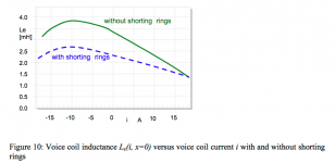
Strange. Inductance vs current, x =0.
What frequency? Who cares what the DC inductance is???
To measure this, inductance vs x is required. Also, frequency dependence.
L vs f vs X vs I vs velocity..It's just a five dimensional problem, what's so difficult?
This is nothing..try eleven dimensions.
Jn
That's a misleading statement. diyAudio is no worse to professionals than than to any other members. There are many professionals here regularly, some under assumed names. The forum is actually much harder on newbies than it is on pros. Please do not spread misinformation.There is a tremendous level of misunderstanding here at DIY, mostly because the professionals don't come here very often. DIY is not nice to them so they leave.
would this be a factor if the enclosure was a horn?I am wondering to what extent I can shape the driver impedance through enclosure design.
would this be a factor if the enclosure was a horn?
Really two issues.
First for sure, "the enclosure" (sometimes called "the suspension") greatly influences the cone motion at low frequencies (which is where we care about it mostly) which greatly influences back-EMF and all the various secondary and error influences discussed in recent posts.
Second, it must be kept in mind that cone motion (and hence VC impedance) and sound output can be wildly discrepant (as with some tuned systems like bass-reflex or TL and with open baffles). The potential for discrepancy is always an issue with motional feedback design, for obvious reasons, and likewise for the current versus voltage amp issue.
Just looking at horns, depends on whether it is an ideal horn (which is a great way to improve the acoustic impedance match of the motor to the air) or a real-world horn (which has bumps in the curve).
B.
Last edited:
would this be a factor if the enclosure was a horn?
I am trying to defer using horns until I really have to. Looking at the CSD plots. My test units show pretty uniform decay, but not fast enough, and I have not figured out a way to make it sound cleaner without introducing other trade offs. Back loaded horn could be an option, but has nothing to do with flattening the impedance.
Currently I do have a transmission line type enclosure that moves the impedance hump below Driver Fo, so that is not too bad as it becomes a protection feature for voltage amps. But trying to figure out how to design for any driver is a pain.
My concern is w/r to our ability to discern ITD/IID. At 1k, we're pretty much 2 microsecond ITD beasts. With one speaker getting the 100 hz and the other not, is the FFT capable enough to see what we localize?
As well, driver displacement can easily surpass 2 uSec physically. Sigh.
I'm glad I only listen casually, this imaging thing would drive me nuts, sitting in one place to hear music...
Jn
You have to remember that localization depends on both ITD and ILD and the ratio varies across frequency. So it's not just ITD that matters. But, yes, an FFT can give us enough resolution to investigate localization. FFT resolution is not a fixed thing, it depends on the parameters used. 2 microseconds is not hard to resolve as a phase shift at 1 kHz. And because a speaker can shift by 2 uSec. does not mean that the ITD will shift by this same amount.
A good system design does not require one to have a "head in a vise". It is possible to design a system such that great imaging is achieved across a 6-8 foot seating area. In this case, the results have more to do with ILD that ITD. There is a know tradeoff between ITD and ILD (see Blauert.)
I talked with my friend who is head of R&D at a major loudspeaker company and he confirmed that the dual voice does does lower the inductance (but not as much as hoped), linearize it WRT excursion and linearize the dissipation as well. That said, his company does not do it because the extra cost is not justified by the subjective performance improvement. Kind of a business decision.
Last edited:
a real-world horn (which has bumps in the curve).
B.
Not always. Mine have no "bumps" in them except for the drivers impedance. It all depends on how well the reflection from the mouth is handled in the design.
You have to remember that localization depends on both ITD and ILD and the ratio varies across frequency. So it's not just ITD that matters. But, yes, an FFT can give us enough resolution to investigate localization. FFT resolution is not a fixed thing, it depends on the parameters used. 2 microseconds is not hard to resolve as a phase shift at 1 kHz. And because a speaker can shift by 2 uSec. does not mean that the ITD will shift by this same amount.
IID is ILD, my acronym uses intensity, yours level.. we are indeed saying the same thing.
I went through that exercise when I found my headphones were giving me weird imaging issues. Turned out the soundcard had one D/A, the interchannel delay shifted some of the image and level was incapable of centering everything properly. edit: I've actually found that it is possible to image a point source very accurately despite a large ILD. But that was a point source, not two speakers.A good system design does not require one to have a "head in a vise". It is possible to design a system such that great imaging is achieved across a 6-8 foot seating area. In this case, the results have more to do with ILD that ITD. There is a know tradeoff between ITD and ILD (see Blauert.)
I talked with my friend who is head of R&D at a major loudspeaker company and he confirmed that the dual voice does does lower the inductance (but not as much as hoped), linearize it WRT excursion and linearize the dissipation as well. That said, his company does not do it because the extra cost is not justified by the subjective performance improvement. Kind of a business decision.
I would agree, for a large manu, the incremental gain just not worth it, nobody's going to buy a driver at twice the cost with minimal improvement.
The inductance not lowering as much as hoped is an interesting statement. I guess he couldn't change the reluctance sufficiently, and he doubled the gap volume with two voice coils. Certainly couldn't reduce gap volume without compromising reliability, tolerances bite us that way.
But I wasn't talking about dual vc's, just dual magnetic circuits, one on each side of the cone. (or stated better, on each end of the vc such that it is physically captured by the return irons.)
jn
Last edited:
In post #2, the yellow trace is the unhoused driver and the green trace with the bump at 8 Hz (and elsewhere) is in the labyrinth. (Compare to the 7-Ohm trace, not the uncalibrated Y-axis.)I am trying to defer using horns until I really have to. Looking at the CSD plots. My test units show pretty uniform decay, but not fast enough, and I have not figured out a way to make it sound cleaner without introducing other trade offs. Back loaded horn could be an option, but has nothing to do with flattening the impedance.
Currently I do have a transmission line type enclosure that moves the impedance hump below Driver Fo, so that is not too bad as it becomes a protection feature for voltage amps....
17 foot pipe sub 12-230 Hz ±5dB
B.
- Status
- Not open for further replies.
- Home
- Amplifiers
- Solid State
- Back-EMF and flat impedance