it would be helpful if you can describe/sketch in detail how you did wiring from diode bridge(s) to cap bank and then to pcbs
I see it as potentially fishy but I can't be sure from posted pics
I see it as potentially fishy but I can't be sure from posted pics
GNDs - it should help you to get clean GND reference to FE pcb
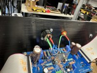
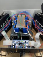
see attached pic - small red dot, pointed with yellow arrow, exactly in middle of 2 caps, ditto on edge - hopefully out of pulsating currents routes
where red dot is, drill small hole for M3 or M4 or whatever small bolt size, take your GND wires for FE from that point
I assume those caps are final ones in Cap bank, and there you have (where red dot is) some tiny area where are no current pulses
now, xformer hum - if everything is wired properly, amps are making music ( so functional), just one sole conclusion possible
what sum Iq you have now set?
Yes - humming in speakers and xformer.I've seen your e-mail yesterday
I will drag the scope out to the garage tomorrow and look at the rails.
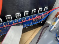
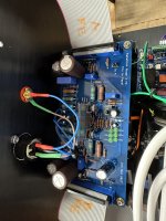
See pictures below for bridges to cap bank (and also front ent). Cap bank to pcbs is 4 runs of 16 awg for each pad on the pcb.it would be helpful if you can describe/sketch in detail how you did wiring from diode bridge(s) to cap bank and then to pcbs
I see it as potentially fishy but I can't be sure from posted pics
Attachments

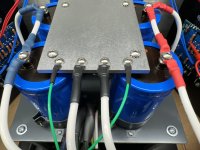
Interesting, never thought about pulsating currents through the plate, plate is 3/16" aluminum.GNDs - it should help you to get clean GND reference to FE pcb
see attached pic - small red dot, pointed with yellow arrow, exactly in middle of 2 caps, ditto on edge - hopefully out of pulsating currents routes
where red dot is, drill small hole for M3 or M4 or whatever small bolt size, take your GND wires for FE from that point
I assume those caps are final ones in Cap bank, and there you have (where red dot is) some tiny area where are no current pulses
now, xformer hum - if everything is wired properly, amps are making music ( so functional), just one sole conclusion possible
what sum Iq you have now set?
Iq right now is about 7.6A, 0.38A per vertical pair (0.58V across 1.5R). I figured I would dial it to where we need to be once in final configuration case wise.
try sorting GND reference, I hope it'll reduce/kill speaker hum
then bias Iq down as low as you can, and observe xformer hum
inform here
then bias Iq down as low as you can, and observe xformer hum
inform here
Thanks for all the attention so far, appreciated as always. Realistically I will not be able to modify the ground plate until this coming weekend (too many family/work items on the list), but wanted to try to document the response here:
1 - Reduced Iq - With all three trimmers at their minimum setting, lowest I can get is about 0.46V across 1.5R, 0.31A per vertical pair or 6.1A Iq. Both transformer and speakers still humming. Also not enough bias here to play music. Relative offset here is essentially 0mV. DC offset is 21V. Without the speaker connected the mechanical transformer hum is not terrible, if the case was all buttoned up, would probably be not noticeable from 4-5 feet away. Maybe DC on the AC line? Another thing to check.
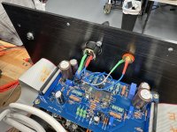
2 - Trimmer response - Wanted to capture this to make sure it is right.
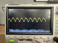
3 - PS Ripple - Getting 100mV on pos and neg rails (see attached). About 400mV before the resistor.
4 - Bridges are Saligny Power, based on LT4320, I needed all the voltage I could get with 17.5V secondaries.
I'll tackle relocating the FE power ground this weekend.
1 - Reduced Iq - With all three trimmers at their minimum setting, lowest I can get is about 0.46V across 1.5R, 0.31A per vertical pair or 6.1A Iq. Both transformer and speakers still humming. Also not enough bias here to play music. Relative offset here is essentially 0mV. DC offset is 21V. Without the speaker connected the mechanical transformer hum is not terrible, if the case was all buttoned up, would probably be not noticeable from 4-5 feet away. Maybe DC on the AC line? Another thing to check.
2 - Trimmer response - Wanted to capture this to make sure it is right.
- Start with all three at minimum. No load on speaker outputs and inputs open.
- On initial startup, 0.46V across 1.5R, Relative offset essentially 0mV. DC offset is 21V.
- Increase TP2 until DC offset hits point where it drops rapidly to ~300mV. At same point, Iq jumps to 0.56V across 1.5R. Relative offset about 30mV. TP3 and TP4 still at minimum. Xfrmr humming slightly, no speaker connected.
- Let it warm up
- Adjust TP3/4 to match Iq on both channels exactly, only need to raise one side by a turn or so (less than 0.01V). Relative offset still about 30mV. DC Offset about 350mV.
- Shut Down, hook up speaker. Inputs shorted, fire up, speaker still hums. Balanced input connected from DAC, music plays fine... with buzz.
3 - PS Ripple - Getting 100mV on pos and neg rails (see attached). About 400mV before the resistor.
4 - Bridges are Saligny Power, based on LT4320, I needed all the voltage I could get with 17.5V secondaries.
I'll tackle relocating the FE power ground this weekend.
Attachments
implemented servo action results in DC Offset (as you call it) in range of 300-350mV, from cold state to temp. equilibrium
functionally, same good as getting it to 0, and it'll be major complication to actually achieve that
edit: as presented in post #20 https://www.diyaudio.com/community/...h-x-servo-for-greedy-boyz.318319/post-5329825
anyway, let's wait to rearrange that GND take-out point ....... as you have now, it's practically dirtiest possible place to get GND from
🙂 Trying to us the consistent terminology! Outside of the buzz, I think everything is responding per design.
All right, updated FE ground complete and we're still buzzing unfortunately. m4a sound file in the zip. I have the option of moving these output stages over to the other PS/FE for the other channel and seeing if I get the same issue there.
Attachments

I know I am not of much help but I will say that you have yourself a beautiful-looking amp! I am really excited to see what you think of the sound after you get it functioning 100%
-Are all of the ribbon connector solder points good? I know those can be tricky. Clean all of the flux off of the solder points and inspect carefully.
-Did you have to make the ribbons yourself? You can check for continuity on both sides on each wire going across. Or just swap the ribbons from the good channel
-You can check the parts and that the active and passive components are all of the correct values etc.
-Check the resistance between the signal ground and chassis ground on both the good channel and the buzzing channel
-Did you go in with a chop stick to tap and push on the components gently?
I listened to the recording. It sounds like some grounding issue or power supply noise to me. Moving the bussing parts to the other power supply does seem like a reasonable thing to try but it would be good to let the Mighty Zen Master pitch a few thoughts.
it doesn't sound as oscillation, nor it sound as servo struggling ...... it exactly sounds as garbage with base frequency of 120Hz
Mike - any malfunction of ribbon cables would prevent proper biasing of OS pcbs, and amp function in general
I believe I sent those with rest of parts in package
anyhow - what I'm thinking now ....... those 2 white wires with black heatshrink bands, connected from bridges to GND plate
maybe just for giggles and temporary, to test nature of evident Gremlins - try disconnecting them from present position of GND plate and improvise how to extend them - then connect them to GND screws of last caps in chain - all the way back, where you moved GND takeout wire
so, one white/black to left cap GND screw, second white/black to right cap GND screw
and yes, wire going from GND to chassis (hopefully with NTC inserted) - it needs to be moved also all the way back, to clean GND point

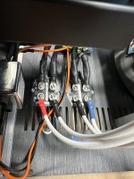
OK - Temporary wiring from bridges to final cap ground complete and chassis ground (which goes through CL60) also moved back. Hum is better, but still there. I should have measured to determine difference, but can do that later.
So is there a better solution than the ground plate? Should I try to establish a star ground instead?
So is there a better solution than the ground plate? Should I try to establish a star ground instead?
Attachments
Nice! Glad you assembled it!
I know from experience with those ideal bridge rectifiers, having used them in many class A, that under a much higher load than a class AB amplifier, I’ve had transformers buzzing (even encapsulated ones) and getting very hot after a couple hours, also causing hum in speakers. I had to change the mosfets on the rectifiers (tried different ones) to get it to quiet down a lot. My suggestion for you is to try a regular bridge to test everything and if you conclude that it is the issue, then you can address the ideal bridges afterwards. Also, low ESR and high ripple caps just after the ideal bridges don’t help.
Do
With your ground plate, the bridge ground connections should be at the "dirty" end of the plate. In other words, leave them at their original location.
The CL60 to chassis and the ground to audio board stay at the "clean" end.
The CL60 to chassis and the ground to audio board stay at the "clean" end.
Yes, Ben, that's logical ...... but we needed to try different option to get as much facts is possible
and, contrary to logic, hum is smaller as pictured in #296
now - I can see only trying common type of bridges (50A quad thingies) instead of fancy ones, then - if better - try initial position of white/black wires, or leaving them on clean side too
and, contrary to logic, hum is smaller as pictured in #296
now - I can see only trying common type of bridges (50A quad thingies) instead of fancy ones, then - if better - try initial position of white/black wires, or leaving them on clean side too
- Home
- Amplifiers
- Pass Labs
- Babelfish XJ , or JX …….. or whatever (Aleph X servo for Greedy Boyz)