5U/500 ... That is a chonky case.
450mm x 500mm external
360mm x 450mm internal
210mm height
18.5 kg
Zeno Mod, how should mosfets be matched for small BJX?
450mm x 500mm external
360mm x 450mm internal
210mm height
18.5 kg
Zeno Mod, how should mosfets be matched for small BJX?
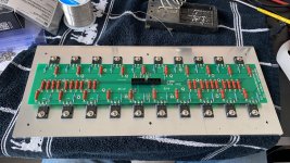
forgot to say - for "small" one - you need 4 quintets (groups of 5 matched mosfets) per channel
closer (in Ugs value) two quintets goes in lower rail position (left and right) , close (in Ugs value) two quintets goes in upper rail position (left and right)
source resistors and (series) output sense resistors are all 1R in value (contrary to big one , where 1R5 are used)
closer (in Ugs value) two quintets goes in lower rail position (left and right) , close (in Ugs value) two quintets goes in upper rail position (left and right)
source resistors and (series) output sense resistors are all 1R in value (contrary to big one , where 1R5 are used)
Thank you for detailed answer!
I can't afford to make monoblocks.
But Mini BJX, I think I can make it to full completion.. hmmm.
I can't afford to make monoblocks.
But Mini BJX, I think I can make it to full completion.. hmmm.
Zen Mod,
Is 130 W heat per channel maximum we can dissipate with 5U/500
40mm Heatsink Information – diyAudio Store
https://cdn.shopify.com/s/files/1/1...o_potenze_dissipanti.pdf?12500389275417700142
Is 130 W heat per channel maximum we can dissipate with 5U/500
40mm Heatsink Information – diyAudio Store
https://cdn.shopify.com/s/files/1/1...o_potenze_dissipanti.pdf?12500389275417700142
remember that base is still Aleph circuit, so amp not being able to leave A class envelope
big one was 100W/8R and 70W/4R
smaller one, if contained to -say - 130W of heat per channel ( possible in big 5U/500) will end in some 50W/8R and 35W/4R
heat/power ratio better than non-xed Aleph, but you can't beat physics
Robert (my guy from Poland, owner of big ones) chose that as his personal preference over numerous original PL amps, all of them being able to cross in B class, so practically unlimited power ..... at least when talking about biggies ( and he tried them in his system while deciding what to buy)
well, 130W figure, I got that as minimum in which I can squeeze one small babelfish XJ channel, not as max figure for 5U/500
I can say that I have enough of in vivo experience with 4U/300, 4U/400, 5U/400 (but I can't remember that I had 5U/500 at my bench) , so my estimate of safe 150W heat per side , for 5U/500 is more or less eyeballed, but I'm pretty confident ........
take in account that - when I say enough - my stance is based on fanless use in Winter time, while Babysitter help in Summer time is always welcome
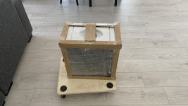

From AliExpress indeed.
Picture did not show the full package.
Arrived in very large box, see pict.
But of course, there is always risk for damage, especially with air freight
.
Picture did not show the full package.
Arrived in very large box, see pict.
But of course, there is always risk for damage, especially with air freight
.
Attachments

Last edited:
Getting there
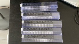
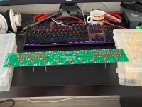
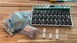
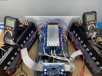
Fun project.
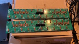
Finished the MOSFET matching, output boards for one channel and the driver boards.
Tomorrow I receive the PSU PCB's so I can start building those.
.
Fun project.
Finished the MOSFET matching, output boards for one channel and the driver boards.
Tomorrow I receive the PSU PCB's so I can start building those.
.
Attachments

Finished, some questions about the circuit
Hi Zen Mod,
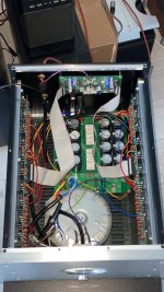
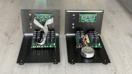
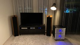
The project is done. Was a lot of work and cost, but the sound is really nice. And bigger is better 🙂
Thanks a lot for the PCB's, they where a big help.
This project invites to experiment a little more. After studying the schematics for a long time, I have some questions.
1) From the servo R36 injects the servo signal into the circuit. R36 is listed as 1.5k. This value seems very low, I'm worried this will inject power supply noise into the circuit. Would 10k-20k value not better? Even with 22k, the servo would still be able to inject 1 mA into the circuit (is 10% of the CCS current).
2) In the servo, Q11 base is directly connected to ground. When the amp fails and sends + rail voltage to the output, Q11 will be reversed biassed and Q11 or both transistors would fail (I had this once). Would it better to insert a 10k resistor between the base and ground to limit the reversed current?
3) For C12 (input servo to gnd) would it be better to use bi-polar cap?
4) What is the purpose of Q8 / Q2? They limit the voltage over the drivers but are not real cascodes. The total dissipation seem not an issue (20mA * 24V is around 0.5W). It would make the circuit simpler.
5) You included BD139 from NXP with the PCB's. Those work. But if I replace them in the driver position with On Semi BD139-16 (those have isolated backs, so easier to use), the circuit oscillates. Is this because of the higher current gain? What is the best way to fix this oscillation, cap over the GD of the outputs? The NXP's seems no longer being produced...
6) (added later) In the output board, what to do with the W1- W2 connections? Ty them together? I tried both with no obvious difference.
I'm very happy with my new amps, they really sound great. The above is more from engineering curiosity as I don't feel the need to improve the sound quality.
Rob
Hi Zen Mod,
The project is done. Was a lot of work and cost, but the sound is really nice. And bigger is better 🙂
Thanks a lot for the PCB's, they where a big help.
This project invites to experiment a little more. After studying the schematics for a long time, I have some questions.
1) From the servo R36 injects the servo signal into the circuit. R36 is listed as 1.5k. This value seems very low, I'm worried this will inject power supply noise into the circuit. Would 10k-20k value not better? Even with 22k, the servo would still be able to inject 1 mA into the circuit (is 10% of the CCS current).
2) In the servo, Q11 base is directly connected to ground. When the amp fails and sends + rail voltage to the output, Q11 will be reversed biassed and Q11 or both transistors would fail (I had this once). Would it better to insert a 10k resistor between the base and ground to limit the reversed current?
3) For C12 (input servo to gnd) would it be better to use bi-polar cap?
4) What is the purpose of Q8 / Q2? They limit the voltage over the drivers but are not real cascodes. The total dissipation seem not an issue (20mA * 24V is around 0.5W). It would make the circuit simpler.
5) You included BD139 from NXP with the PCB's. Those work. But if I replace them in the driver position with On Semi BD139-16 (those have isolated backs, so easier to use), the circuit oscillates. Is this because of the higher current gain? What is the best way to fix this oscillation, cap over the GD of the outputs? The NXP's seems no longer being produced...
6) (added later) In the output board, what to do with the W1- W2 connections? Ty them together? I tried both with no obvious difference.
I'm very happy with my new amps, they really sound great. The above is more from engineering curiosity as I don't feel the need to improve the sound quality.
Rob
Attachments
Last edited:
Hi Zen Mod,
The project is done. Was a lot of work and cost, but the sound is really nice. And bigger is better 🙂
Thanks a lot for the PCB's, they where a big help.
This project invites to experiment a little more. After studying the schematics for a long time, I have some questions.
1) From the servo R36 injects the servo signal into the circuit. R36 is listed as 1.5k. This value seems very low, I'm worried this will inject power supply noise into the circuit. Would 10k-20k value not better? Even with 22k, the servo would still be able to inject 1 mA into the circuit (is 10% of the CCS current).
2) In the servo, Q11 base is directly connected to ground. When the amp fails and sends + rail voltage to the output, Q11 will be reversed biassed and Q11 or both transistors would fail (I had this once). Would it better to insert a 10k resistor between the base and ground to limit the reversed current?
3) For C12 (input servo to gnd) would it be better to use bi-polar cap?
4) What is the purpose of Q8 / Q2? They limit the voltage over the drivers but are not real cascodes. The total dissipation seem not an issue (20mA * 24V is around 0.5W). It would make the circuit simpler.
5) You included BD139 from NXP with the PCB's. Those work. But if I replace them in the driver position with On Semi BD139-16 (those have isolated backs, so easier to use), the circuit oscillates. Is this because of the higher current gain? What is the best way to fix this oscillation, cap over the GD of the outputs? The NXP's seems no longer being produced...
6) (added later) In the output board, what to do with the W1- W2 connections? Ty them together? I tried both with no obvious difference.
I'm very happy with my new amps, they really sound great. The above is more from engineering curiosity as I don't feel the need to improve the sound quality.
Rob
well, for proper Fugly! , I'm expecting to see full pictures ........ even if we know that you fed case cloning facilities, buying that cases ...... I know it is sacrilege, but I also know how tempting is to have something resembling result of Papa's funny Aura ......... I did recognize phenomena - general level of Humor in one's house is increased with increased number of Papamps in same house

go figure from where that's coming ........
1. amp is X in configuration, so you can beat it with AC for entire day, whichever corner you choose, due to config, hardly any of that beating is shown on speaker outputs; if you increase 1K5 value, that's resulting in increasing current through "other" bjt in LTP, and decreasing current though left LTP bjt, thus decreasing useful range of action
2. if amp fails, I'm having much bigger problems than replacing those two small bjts
3. naah .........
4.LED String was looking sorta unemployed, while doing only job of biasing JFET LTP bjt cascodes, so I came with overbrilliant idea to add something as second job for said LED string , so now it's also serving as biasing mech for emiter followers, and I can proudly say that I put cascoded emiter followers there .........
 - why not - in the end - there is lesser cold to hot change in weeny BD
5. nothing what strategically placed 1-10nF from B to C of lower BDs can't cure ; you can put same on BD cascodes too
6. leave W pads unconnected!! ; these are for some possible later use of pcbs....... one of usual ZM's Lucida Intervala ...... I did forgot for at least of 50% of them what was my intention
when you have more hours with amps singing, write again about impressions

Hi Zen Mod,
Thanks for the answers.
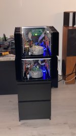
Yes I'm guilty... and tried to hide the front of the cases in the pictures 🙂
My excuse is that it is hard to find another case capable of such dissipation. The other option was a large case (from similar source) that said 'Mark L...' on it. Seems not right to build this amp in a ML clone case.
Also made sure there was no PL logo on my cases. But still... a different front would be more.... correct.
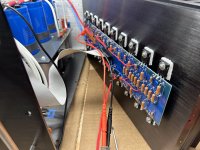
Anyway, about the 'W' points, my 'point' is that the output area is split on the PCB, so there are 4 groups of 5 mosfets on the PCB (nice to make smaller amp). So I thought I should connect those W's together to get 2 groups of 10 mosfets. You're sure I should not connect them together on the same PCB?
Included final picts.
Thanks for the answers.
Yes I'm guilty... and tried to hide the front of the cases in the pictures 🙂
My excuse is that it is hard to find another case capable of such dissipation. The other option was a large case (from similar source) that said 'Mark L...' on it. Seems not right to build this amp in a ML clone case.
Also made sure there was no PL logo on my cases. But still... a different front would be more.... correct.
Anyway, about the 'W' points, my 'point' is that the output area is split on the PCB, so there are 4 groups of 5 mosfets on the PCB (nice to make smaller amp). So I thought I should connect those W's together to get 2 groups of 10 mosfets. You're sure I should not connect them together on the same PCB?
Included final picts.
Attachments
well. two W pads - you can connect them with fat wire bridge, but they're effectively already connected through all Source resistors and through two output resistors groups
when you route one wire from each ( of 4) S pad ( SA, SA', SB, SB') to one output terminal ( so 4 wires meeting at output terminal) , two output resistors groups are practically in parallel
there is slight principal difference with and without bridging two W pads, but as you already tested - there is no practical difference in vivo
btw. that W (dis)connection is deliberately made - you certainly guessed it already - to be able to use same OS pcb for smaller iteration - one OS pcb for all 4 quadrants needed for one channel
enjoy!
and, yes, FFFugly!
don't forget to write big letter to Pa
...... And bigger is better 🙂...........
by my own experience ...... of utmost verity - when applied on speakers
then you can go wild and build even meaner small amp(s)
though, every proper Home must have at least 3 Papamps, of different variety, so Big Ones aren't redundant
🙂
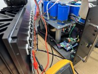
Hi all - bringing this one back for 2024. Picked up Do's project a while back and decided last summer to start in earnest in collecting the balance of the parts to finish this build. Few basics of what I have here:
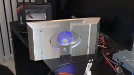
1 - Yes a clone wars case, trying to differentiate it a bit on the front, removed the meter/added acrylic to see inside the amp, etc. Will post more pics later once up and running.
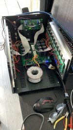
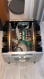
2 - Power Supply - Toroidy 1200VA, 4x17.5V secondaries, getting about 22.5VDC loaded at ~8A per rail. CRC is 64mF-64mf-0R1-64mF. Fancy Saligny Power bridges. Softstart from Neurochrome.
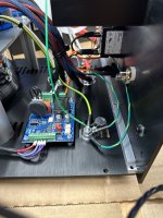
Fired it up yesterday for the first time, everything acted as expected, adjusted the bias/offset, smooth, no issues. Plays music, but... hum... Transformer and speakers. Few pictures below if any eagle eyes spot any issues. When I tested the PS, I had it loaded at about 2A per rail with DC light bulbs and the transformer was mechanically silent. I can probably test it up to 6A per rail. Ideas to troubleshoot always welcome!
1 - Yes a clone wars case, trying to differentiate it a bit on the front, removed the meter/added acrylic to see inside the amp, etc. Will post more pics later once up and running.
2 - Power Supply - Toroidy 1200VA, 4x17.5V secondaries, getting about 22.5VDC loaded at ~8A per rail. CRC is 64mF-64mf-0R1-64mF. Fancy Saligny Power bridges. Softstart from Neurochrome.
Fired it up yesterday for the first time, everything acted as expected, adjusted the bias/offset, smooth, no issues. Plays music, but... hum... Transformer and speakers. Few pictures below if any eagle eyes spot any issues. When I tested the PS, I had it loaded at about 2A per rail with DC light bulbs and the transformer was mechanically silent. I can probably test it up to 6A per rail. Ideas to troubleshoot always welcome!
Attachments

I have been waiting for the day that someone builds another one of these! The Clone Wars cases are unreasonably nice... It is hard to go with something else. There really isn't another option that will dissipate the heat that these amps make unfortunantly.
Can you show pictures of how the inputs are connected to the board and the back panel? Also, close pictures of the front end boards etc.
Can you show pictures of how the inputs are connected to the board and the back panel? Also, close pictures of the front end boards etc.
Hi all
I've seen your e-mail yesterday but as I wasn't at home (nor workshop) didn't had necessary files on disposal, so delayed reply
Got home sort of delayed........ and I see that you had sort of successful powering up session
Now, clarify - you have both humming xformers and also hum in speakers?
is there hum in speakers with shorted inputs?
do you have a scope to observe what sort of juice is getting to channel pbs?
as amp is bridged, it is having sort of self-cancelation of rail's garbage, but there are the limits even to that
- Home
- Amplifiers
- Pass Labs
- Babelfish XJ , or JX …….. or whatever (Aleph X servo for Greedy Boyz)