in original, all GND wires were on dirt end
then , wires going to FE and chassis are moved to clean end and buzz was still there
then I suggested moving GND wires from bridges also to clean end, to determine is there difference or not
now, existing bridges are left as sole problematic
then , wires going to FE and chassis are moved to clean end and buzz was still there
then I suggested moving GND wires from bridges also to clean end, to determine is there difference or not
now, existing bridges are left as sole problematic
I see an iteration where the FE ground was connected to the clean end but the CL60 to chassis was connected to the dirty end. Would that make a difference?
everything is worth trying
when I made "first one", I was sort of obliged to use cap bank at hand, but wired it properly, in context
dead as Dodo without signal
when I made "first one", I was sort of obliged to use cap bank at hand, but wired it properly, in context
dead as Dodo without signal
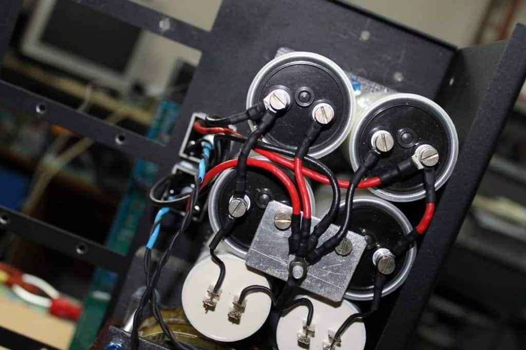
Here is where I am at with my Stasis build so far. I guess there is a clean end where the motor run caps are attached. The rectifiers are VBE60-06A diode bridges in the SOT-227 puck package. Static testing looks good with low ripple on the clean rails.
Attachments
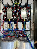
though, I always prefer longer tail on plate on clean end, allows more clearance between clean GND central point and pulsating paths
example; slightly different arrangement of GND routes (wires - all connected to one central point) but possible due to fact that amp in question is having pretty much symmetrical rail loading/current distribution
example; slightly different arrangement of GND routes (wires - all connected to one central point) but possible due to fact that amp in question is having pretty much symmetrical rail loading/current distribution
OK Thanks guys. Any recommendations on how to measure the magnitude of the speaker hum? Very crude test just completed using dB meter app on iphone:
Inputs shorted.
All Bridge, Chassis and FE GND connections at the 'clean' end - 43dB at the woofer on cheapo shop speakers. Woofer is louder than tweeter.
Bridge GND connected to 'dirty' end and FE and Chassis GND at 'clean' end - 40db at the woofer.
I also sent an Email to Evotronix to have them weigh in on thoughts that the bridges could be a culprit. Can't seem to find anything appropriately sized laying around, so I'll have to order some new bridges to try that option.
MZM: why must the bridges be the culprits? Yes normally that would be the case. But what about the transformer? I rebuilt my BA-3 several times, but only when I trashed the transformer did the humbuzz disappear.
well, I'm pretty familiar how big honking old type briges are behaving, be it fancy or those for us wearing pitchforks, but I don't know how those exact uberfancy are behaving when heavy loaded
and in this situation, I'm sorta in Dr. Haus Tribe, as long all facts aren't revealed
it is disqualification game, replacing link by link should reveal weakest one
and if in the end xformers are still buzzing, but with properly decreased speaker hum, then you have only xformers to replace
now, as far I can remember, I had buzzing xformers but when PSU really sorted, it wasn't so bad to influence speaker output severely

Enlightening, as always! Thank you.
And, to add, I only replaced the tranformer when I hand built that P2P PSU under your guidance, so I didn’t replace just the transformer. So I cannot say with absolute certainty it was the (only) culprit. And in addition, the ground layout on the stores PSU boards is… well.
A funny note to add, is that with the new PSU, I can take ground from just about anywhere on the plane and it is still dead quiet. All componentns MZM approved, sans the trannies which the mighty one despises (Toroidy)
Good eye Ben, as usual. His orientation is the opposite of what the reverends (you and MZM amongst) teach here at the forum.
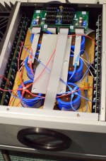
In that picture from the PL amp, a few relevant things to notice: 1: The filtering orientation is from front to back, 2: The bridges are likely under it all along with the tranny - far away from FE and signals and 3: there is an extra set of caps before the takeoffs/2 sets after filtering, 4: audio gnd is taken from the second set of caps, not at the end (like MZM suggests and like I also did it). Observation 4 doesn’t nescessarily suggest that is the best place for a takeoff (physically it should not be ideal), merely that it is a possibly quiet takeoff point, given a good PSU.
The trick of depicted amp is probably the oldest in the book: good parts of proper rating that work well together, good layout, and a huge amount of capacitance - an extra stock of it after filtering - Papa style. Makes for an amp not in need of Schottky’s and other fancinesses.
I can rebuild another one,
don't do anything else now, besides trying common type diode bridges
if you don't have them in drawer, it costs some to test, but negligible comparing to what you already invested
The perfect ones you had me buy cost the same as the standard 35A’s that most people around here use, iow el cheapo compared to all competition.
In that picture from the PL amp
me thinks you got it wrong
from bridges it goes as CCRC
rails takeout from last C
GND takeout somewhere where I can't see it, but from other pictures I believe it is not from cleanest possible point but most likely wasn't critical so ...... Papa is known for not too much obsessing, once when he's close to predefined goals

Yes, I think you are right. Seems I got it all backwards. Or maybe midwards? 🤣 Smart move to put the dirty DC into the second set of caps and keep it away from the FE.me thinks you got it wrong
from bridges it goes as CCRC
rails takeout from last C
GND takeout somewhere where I can't see it, but from other pictures I believe it is not from cleanest possible point but most likely wasn't critical so ...... Papa is known for not too much obsessing, once when he's close to predefined goals
Yes. Well, you didn’t HAVE me buy anything, but you suggested them when I suggested something crappier and more expensive
Some plutonium type diodes I believe.Bridges ordered, in the meantime I will work on finishing the 2nd channel to at least make sure that circuit is functioning correctly. Thanks for everything to date, will get there eventually. I'll also pop the FE up away from the bridges to see if any changes in buzz are discernable.
Had some time through the week and this weekend:
1 - Finished the build of the Left Amp. Built it to the same spec as the Right Amp as those were the parts on hand prior to arrival of new bridges. Amp works, responds as designed and plays music fine, but hums through speaker, transformer hum is less than Right Amp.
2 - Right Amp - Removed Evotronix Saligny Bridges and replaced with POWERSEM PSB 82-08. Powered up and speaker still hums same amount. Rails now at ~20V.
3 - Left Amp - Have a 6A rated AC line filter after the switch and before the Neurochorme soft start. Bypassed that and no change to transformer or speaker hum.
- Home
- Amplifiers
- Pass Labs
- Babelfish XJ , or JX …….. or whatever (Aleph X servo for Greedy Boyz)