I was surprised, had it at +-35v before and you didn’t recommend going below +-30. It will go back up after the summer. I can fit TO247 fets to my XA252 so I might give it a try one day.
The bad behaviour when turning the amp off that I had was caused by a dodgy AliExpess smps that would make it thump 4 times.
Using a pair of Mean Well 24v150w in the case now, they are silent and well behaved. I think you can adjust them to 29v.
I’ve been working on this on and off for a few years. A touch screen controller for a preamp or integrated amp. Remote control, balance, 5 inputs, 2 outputs, backlight settings, brightness setting, lots of colour settings, speaker grounding (when turning on and off), changeable input names, adjustable fixed level output (for tv or streamer with its own volume control), adjustable trimmed output (so weak inputs play at the same level as the rest of your gear), aux power (relay that can be set to an input for a DAC or phonopre psu), mute, 0.5dB steps and standby. Uses Opto couplers so any voltage relays can be used. Uses one or two PGA2310 chips for SE or BAL. I have been concentrating on the User Interface and the look of it. I will post a video of it working soon.


I hate smell of burning resistors in morning, smells of defeat. Blatantly stolen and bastardized from Apocalypse Now.
Well.... yeah the thought of that part of the movie has crossed my mind.
For the last month or so, Macho SIT has sat on a shelf... trying to figure out what to do with it. It might morph to an SET version...
Just redid the power supply section on my ZenMod 252 and it fired right back up, no adjustment too bias and offset was still less than 5mv. I built the SET version and it has been rock solid. I did blow out the bd139/140 sandwich but that was totally my fault by not checking the outputs on my miro dac before I hooked it up. Still the best sounding amp of my collection by far(DIY F6 and M2) Currently building a Aleph J but I am sure it wont compare. Kinda thinking I should have just done the MOS version and then added sugar through the preamp or tube I/V setup with a DAC.
I'm lucky bstrd, equally enjoying with or without sugar ....... as long there is 2nd dominant, I'm happy with any amount
though, verboten in my coffee
though, verboten in my coffee
Zenmod, All parts replaced, but have not installed Q1/Q2 sandwich.... should I complete assembly and attempt refire, or leave out Q1 and Q2 for now with short on Q1, whole mess not yet hooked to mosfets and go through tests again? Or just attempt re firing it up?
Russellc
Russellc
should I complete assembly and attempt refire,
I would do that, considering amount of replacements you did
I should show a picture of the back of one of my old modified Stasis front ends, but then people would need to join a support group after seeing the horror.... the back of those boards were a bit... uh ... busy..
The pad lifted? That shouldn't be a huge deal. If you want to use the board, you can run a piece of jumper from the lead off of the BJT to the next part(s) on the schematic.
yeah
Dont have the board in front of me right now, there is a resistor I think R19? looks like it connects. If so, I could replace it, leaving long lead to bring up through messed up pad and solder directly to leg of device.
Yes. The Horror, the horror...I should show a picture of the back of one of my old modified Stasis front ends, but then people would need to join a support group after seeing the horror.... the back of those boards were a bit... uh ... busy..
If it is unrepairable, will just buy another kit, maybe two, I want one for upstairs too, and a spare board ready to go isnt a bad idea!
Looking at schematic and pads, I think I can get this part wired as suggested, but will likely build replacement channel for if/when repair let's go,
Plus I need to build another one for upstairs.
Will get another 5U chassis, wish the special Pass Diy audio custom case was large enough without reducing bias, but this amount in 5U I have now is pretty darn warm!
Incoming email Zenmod!
Russellc
Plus I need to build another one for upstairs.
Will get another 5U chassis, wish the special Pass Diy audio custom case was large enough without reducing bias, but this amount in 5U I have now is pretty darn warm!
Incoming email Zenmod!
Russellc
Bridge the lifted pad and try to make it work.
Considering the amount of pain you suffered with this board, don't stop just now.
At least it'll tell if you can recycle the parts or just trash the whole, not mentioning your skills upgrade.
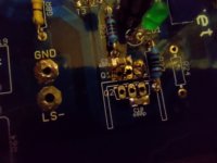
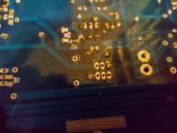
And your last image make me suspicious regarding your soldering method.
HOT iron, fast action, and don't be shy with solder: some pads are not properly covered.
Considering the amount of pain you suffered with this board, don't stop just now.
At least it'll tell if you can recycle the parts or just trash the whole, not mentioning your skills upgrade.
And your last image make me suspicious regarding your soldering method.
HOT iron, fast action, and don't be shy with solder: some pads are not properly covered.
I can solder, problem is those parts, Q1 and Q2 have been in and out SEVERAL times.
Used desoldering station which works fabulous, just last time, pad gave up ghost. Those particular pads are tiny.
They were properly covered, pic is with all the solder sucked off pad. nothing being trashed, I can fix board. I am getting another set for another amp, going to buy one extra channel. Don't like messy boards, but if works, great if not replacement goes in, old board in parts drawer.
Seems it's my turn. I have had a lot of distractions which kept me from paying the necessary attention to test this beauty. Sadly not all easy going. For some reason I have full bias the moment voltage is applied. With 4V on the rails, the bias is already at 200mV, P2 makes no difference. Going to slowly go through the board, whatever I have done, I did to both channels as both behave the exact same way.
- Home
- Amplifiers
- Pass Labs
- Babelfish XA252 / Babelfish XA252 SIT / Babelfish XA252 SET