Was wondering before "board off mosfet" test, does removal of mosfets from circuit in anyway protect R24 from roasting during these measurements? Or is it just as likely to roast?
removing output pucks is part of dilemma solving process
in one moment you started asking yourself - is there a possibility that pucks are damaged?..... and way of solving that question is to remove them and test, where even simple Chinese gizmo tester will do the job
and while there, why not taking opportunity to test entire circuit without them, if nothing else than to be relaxed, knowing that in case of any ookup or mishap, there will be no welding of wires or fireworks ...... at least no big ones
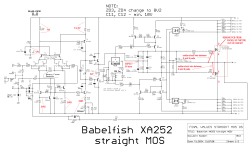
I believe I already posted this ........ some specific measurement points and their values
in one moment you started asking yourself - is there a possibility that pucks are damaged?..... and way of solving that question is to remove them and test, where even simple Chinese gizmo tester will do the job
and while there, why not taking opportunity to test entire circuit without them, if nothing else than to be relaxed, knowing that in case of any ookup or mishap, there will be no welding of wires or fireworks ...... at least no big ones
I believe I already posted this ........ some specific measurement points and their values
Attachments
Yes you did. I remember R19 someone commented about the 3 to 4 volts. Also I keep re reading cwlo's testing results.
I assumed these pucks were bullet proof for these purposes....but fact same apparent damage both channels....one channel fixed one not. All removed parts test fine. Can only assume (with little I know) that something else is dead that survived in the other channel.
Mosfet less measurements should find some anomaly for hopefully final de poofing
Last edited:

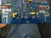
Parts arrived. I was going to solder wire to short G to S, but was afraid if I did it on the pad I might not get all the solder off, making a non smooth surface for mosfet seating against PCB.
Looking at schematic, will this alternative connection work? This is not soldered yet....
Looking at schematic, will this alternative connection work? This is not soldered yet....
Attachments
OK, stirring around, been ill past couple days some bug got me. I will solder this up and power up for measurement cwlo made on his amp. Then can find gremlin hopefully.
Bias full ccw, fuse out of "good" channel. No output mosfets to bias, so hook up variac and get ready to let smoke out or not.
Got started, then stopped. Board in question about to solder up power supply and couple of questions spring to mind. First, it's liable to short against things in this location, and it will be difficult to get to all points needing measured. I don't own a "lab power supply" and of course will be using one in chassis!
Since mosfets not in circuit, is it acceptable to have board outside of chassis on extension wires soldered to Pos, neg and ground from power supply to board?
This makes the uneducated assumption that without mosfets in circuit, not so much amperage involved, or is this incorrect?
If correct ( even blind squirrel finds nut once in a while) my plan was short as practicable extension wires in 14 gauge, only for this test.
I don't see much difference in this arrangement and if board was in same position using some lab power supply. I basically don't know how much juice is in circuit without mosfets, I assume not much?
hooked all up for testing. began to raise voltage, r24 beginning to smoke, off before tanned, but something not right
obviously. this is "off mosfet" test....
obviously. this is "off mosfet" test....
I have two different types of BD 139 and BD 140. One type is like came with kit, with metal backs. I assume this is why mica required.
One type of BD 139 and BD 140 do not have metal back. Would this type work without mica? Just wondering. Wonderiong even more why R24 smokes without mosfets hooked up. What to test next, Im out of tricks.
One type of BD 139 and BD 140 do not have metal back. Would this type work without mica? Just wondering. Wonderiong even more why R24 smokes without mosfets hooked up. What to test next, Im out of tricks.
I have both 139 and 140 in both versions, just so ordered. I knew the kit had metal back and that's fine. Saw the others, not expensive so picked a few pairs in that type. I'm getting better at making the sandwiches and fishing the bolt through mica now!
I will wait for info, sounds like similar test as "no mosfet" test, just in realm of Q1 and Q2.
I could not believe R24 smoked again. Curiosity is up.
I could not believe R24 smoked again. Curiosity is up.
I hate smell of burning resistors in morning, smells of defeat. Blatantly stolen and bastardized from Apocalypse Now.
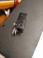
I have Q1 and Q2 removed and waiting further info. The desoldering station was worth price of admission, which was cheap. Instead of a twisted leg mess
that sometimes occurs with normal braid and solder/pult contraptions. Here, removed Q1 and Q2 together in one piece. Looks like not even installed yet!
Ready when you have the numbers, Zenmod what is next?
that sometimes occurs with normal braid and solder/pult contraptions. Here, removed Q1 and Q2 together in one piece. Looks like not even installed yet!
Ready when you have the numbers, Zenmod what is next?
Attachments
Waiting for info and have time finally to attempt repair! As your time allows, no hurry!will post edited schematic of testing just FE sans BD follower; again, trick is to establish NFB path, so circuit have all conditions to be stable
plastic case BD is OK (and no mica needed), though I wouldn't mix plastic with metal in pair, due to diff. TempCo
Russellc
- Home
- Amplifiers
- Pass Labs
- Babelfish XA252 / Babelfish XA252 SIT / Babelfish XA252 SET