usual drill - checking that all positions are populated with proper component/value/orientation
I've made all possible mistakes there (not with XA252, luckily) - just as example - had crossed polarities of outputs, just one polarity instead of mixed, other one polarity instead of mixed etc.
and that's just what's possible with outputs

I've made all possible mistakes there (not with XA252, luckily) - just as example - had crossed polarities of outputs, just one polarity instead of mixed, other one polarity instead of mixed etc.
and that's just what's possible with outputs

Yep, I checked all parts before starting to build and copied left to right as I built. But built in short times when I had option to build (not how I like to build = much prefer dedicating a full day and just burning through flux)
Very glad both channels do same thing, good thing is that it all seems to be working otherwise, rails equal, offset starts at 1 to 2 V but comes down as I crank variac, stopped turning up beyond 4 to 5 volts because of massive current draw, will make fuse smaller next time I try.
Parts around ccs look OK, but much more to check still.
This will be slow going.
.. dB


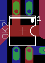
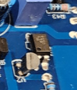
I had impression that optos are rotated, but no..........
just in case, as confirmation that they're OK, attached files
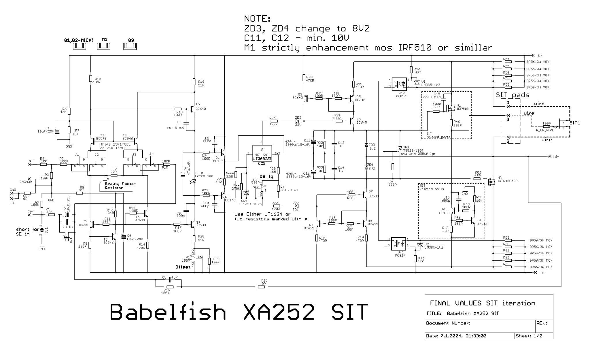
schm for your option is, from post #1462
proper optos are PC817C, through hole
example: https://www.tme.eu/Document/7534c9f89aa4b1eba4ec90182e378328/PC817_2_3_47.pdf
edit: as I can see, even if you rotate those optos you have, pin 1 is not going to be
just in case, as confirmation that they're OK, attached files
schm for your option is, from post #1462
proper optos are PC817C, through hole
example: https://www.tme.eu/Document/7534c9f89aa4b1eba4ec90182e378328/PC817_2_3_47.pdf
edit: as I can see, even if you rotate those optos you have, pin 1 is not going to be
Attachments

Last edited:
here it is, proper cummulative schm for your iteration of pcbs, even if I'm sure that I sent you pack of files:

but, I think I found what's problem
instead of bolting wire to G mosfet pad (and not!!!! populating R53), unbolt that wire from G mosfet pad, desolder fat wire from SIT Gate, solder 47R resistor ditto to SIT Gate, thin wire ( heatshrink wire, resistor, gate pin) and solder other end of thin wire to small G pad, near R53
as is now, Gate of SIT is floating, so no wonder that you have drekload of current
Last edited:
well , where would we be without you - the master has served us well once again

both channels up and happy
both channels up and happy
One question, this is a test PSU (standard FW so only 24v) the lowest I can adjust Iq is 117mV which is about 1A. My final PSU is 30V, so I suspect that the lowest Iq is going to be close to 2A. I can easily adjust for higher bias, so I think all is working, just making sure I don't need to add more room for play.
This one has taken too long to pulk together
This one has taken too long to pulk together
just chill
once when you have enough rails that biasing mechanismus is doing its work, there you have it what you set
once when you have enough rails that biasing mechanismus is doing its work, there you have it what you set
Hi ZM,
Are the spectral graphs in the first couple of posts made with a unbalanced or balanced input? https://www.diyaudio.com/community/...-sit-babelfish-xa252-set.373443/#post-6687821
I'm planning to modify my balanced Blowtorch clone to reduce power dissipation, plan is/was to go unbalanced. However need the extra gain in balanced condition OR add gain in the system.
Do you have measuring results of balanced vs unbalanced?
we have initial success

bias at about 1.9A (210mV) with 30V rails - [dual donut, big can caps - cap multiplier]
left for an hour, heatsinks at 42 ( the perfect number ) offset once adjusted initially remained below 5mV
all ready for wiring up and testing with music - thanks mighty zen this has been my "perfect amp" to build for some time.
..dB
HI, been studying circuit and simulating in LTspice.
Regarding: " OK1-OK2-TH1 .......... 10A limiting circuit, Savior of Our Souls, blatantly stolen from Pa 😛 "
Was wondering when it will be of added value. Came to the conclusion that only a short on the output will trip this circuit. Am I correct, or do I mis another failure mode?
Regarding: " OK1-OK2-TH1 .......... 10A limiting circuit, Savior of Our Souls, blatantly stolen from Pa 😛 "
Was wondering when it will be of added value. Came to the conclusion that only a short on the output will trip this circuit. Am I correct, or do I mis another failure mode?
deserves longer reply
typing from phone, so it'll wait 'till tomorrow night, when I'm back home
typing from phone, so it'll wait 'till tomorrow night, when I'm back home
making slow progress
original plan was to keep the original amp format but ... well this is diy and we go with the flow.
so original plan to repurpose the SUMO Andromeda

ended up being a very frankensteined chassis that is still a work in progress - needs a screen at the front and back to fill the gapping hole

Have now been testing for short periods ( ~ 2-4 hours total ) with the test speakers in the basement - HUGE smiles on my face. Clear that this amp has massive slam and control but also the finesse to bring out details.
..dB
original plan was to keep the original amp format but ... well this is diy and we go with the flow.
so original plan to repurpose the SUMO Andromeda
ended up being a very frankensteined chassis that is still a work in progress - needs a screen at the front and back to fill the gapping hole
Have now been testing for short periods ( ~ 2-4 hours total ) with the test speakers in the basement - HUGE smiles on my face. Clear that this amp has massive slam and control but also the finesse to bring out details.
..dB

- Home
- Amplifiers
- Pass Labs
- Babelfish XA252 / Babelfish XA252 SIT / Babelfish XA252 SET