side of R122 being on negative rail is more negative than other side , so cap neg goes there
use ohmmeter to see where it is, I mean - which side of R122 is sitting on neg rail
though, you can try first small cap thingies, these can be cure, while 10uF across R122 is "just" investigation step
you're not polluting the thread, it serves exactly this purpose
use ohmmeter to see where it is, I mean - which side of R122 is sitting on neg rail
though, you can try first small cap thingies, these can be cure, while 10uF across R122 is "just" investigation step
you're not polluting the thread, it serves exactly this purpose
I came across these, and of course they are interesting since Mighty is a great fan of nifty power cables.
Do you think these will be a good match with this amp?
https://www.finn.no/251018723

Do you think these will be a good match with this amp?
https://www.finn.no/251018723
Last edited:


Hi ZM
I did a few things to soothe my OCD and to try to rule out any remaining variables regarding differences between the boards used in both my quiet and noisy amp.
I decided to follow through and shorten all the leads to the transistors on all amp boards so they are the same.
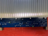
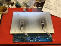
While I had the remaining #2 amp (right) noisy board out, I pulled the #1 amp (right) quiet board and put them side by side to examine closely.
Again, the only difference I could find was the presence of R139 on the #2 amp board.
Since R139 didn’t seem absolutely necessary (based on your previous post) I decided to remove it so that my OCD was convinced I had things as close as possible to identical between the two amp boards.
I did the same thing to the #2 amp (left) channel board…and took side by side pictures of the #1 and #2 left channel boards. I figured I could always remount the R139/239 resistors.
That left me with results I have tried testing over and again several times since I last posted.
The noise was never exactly the same between the left and right channels of the noisy #2 amp.
Both #2 amp channels would make a louder more intense buzzing noise when they were first powered up.
However, the left channel would quiet down very quickly and I would be left with residual humming that when I put my ear close to the test speaker was obviously louder than the #1 amp.
The #2 right channel would continue to buzz more loudly for almost a minute before it would calm down and settle to a similar level as the #2 left channel.
I let the #2 amp sit over night and get cold several times to confirm this behavior before and after changing the wiring and removing the resistors.
It seems like the#2 left channel doesn’t buzz loudly anymore on start up now. It does still have an overall higher noise level than the #1 amp. No idea why this change occurred. The transistor wires had been shortened previously…so the only change was removing R139. I keep testing it to see if it remains consistent from a cold start.
My results with the #2 right channel were different . It continues to buzz loudly when fired up from a cold start. It eventually quiets down to a similar noise level as the #2 left channel.
Consecutive restarts present shorter and shorter periods of loud buzzing on start up.
I also tried installing a 10uf 35V Silmic across R122 of the #2 right channel.
When I fired it up it did NOT buzz loudly…but had a similar overall noise level to the #2 left channel.
I went back to just a 270 Ohm resistor at R122 and the loud buzzing noise at start up came back.
I got hold of some small value (680pf-2.2nf) caps to try in the other locations you suggested.
I’m wondering if you think adding the caps is a “bandaid” fix?
Do you think its possible (for me) to track down the source of this problem?
I did a few things to soothe my OCD and to try to rule out any remaining variables regarding differences between the boards used in both my quiet and noisy amp.
I decided to follow through and shorten all the leads to the transistors on all amp boards so they are the same.
While I had the remaining #2 amp (right) noisy board out, I pulled the #1 amp (right) quiet board and put them side by side to examine closely.
Again, the only difference I could find was the presence of R139 on the #2 amp board.
Since R139 didn’t seem absolutely necessary (based on your previous post) I decided to remove it so that my OCD was convinced I had things as close as possible to identical between the two amp boards.
I did the same thing to the #2 amp (left) channel board…and took side by side pictures of the #1 and #2 left channel boards. I figured I could always remount the R139/239 resistors.
That left me with results I have tried testing over and again several times since I last posted.
The noise was never exactly the same between the left and right channels of the noisy #2 amp.
Both #2 amp channels would make a louder more intense buzzing noise when they were first powered up.
However, the left channel would quiet down very quickly and I would be left with residual humming that when I put my ear close to the test speaker was obviously louder than the #1 amp.
The #2 right channel would continue to buzz more loudly for almost a minute before it would calm down and settle to a similar level as the #2 left channel.
I let the #2 amp sit over night and get cold several times to confirm this behavior before and after changing the wiring and removing the resistors.
It seems like the#2 left channel doesn’t buzz loudly anymore on start up now. It does still have an overall higher noise level than the #1 amp. No idea why this change occurred. The transistor wires had been shortened previously…so the only change was removing R139. I keep testing it to see if it remains consistent from a cold start.
My results with the #2 right channel were different . It continues to buzz loudly when fired up from a cold start. It eventually quiets down to a similar noise level as the #2 left channel.
Consecutive restarts present shorter and shorter periods of loud buzzing on start up.
I also tried installing a 10uf 35V Silmic across R122 of the #2 right channel.
When I fired it up it did NOT buzz loudly…but had a similar overall noise level to the #2 left channel.
I went back to just a 270 Ohm resistor at R122 and the loud buzzing noise at start up came back.
I got hold of some small value (680pf-2.2nf) caps to try in the other locations you suggested.
I’m wondering if you think adding the caps is a “bandaid” fix?
Do you think its possible (for me) to track down the source of this problem?
///////
I’m wondering if you think adding the caps is a “bandaid” fix?
Do you think its possible (for me) to track down the source of this problem?
Gremlins
anyway, what I wrote about small caps - that's not bandaid, it's more as taming da beast
and it'll not have any price regarding sound quality
Chromenuts,
Were you able to verify if touching the chassis had any effect? If it does, perhaps there's a hidden gnd/isolation issue?
Were you able to verify if touching the chassis had any effect? If it does, perhaps there's a hidden gnd/isolation issue?
Hi Dennis
I was not able to verify any affect from touching the amp case.
I think what happened was that I had the amp on long enough listening to the buzzing sound and playing with the test speaker, speaker cables, input wiring and other things and I happen to touch the case when the circuit stabilized and the loud buzzing diminished.
There is a weird affect on the noise from holding the test speaker and/or speaker wires and allowing the wires to touch the concrete floor. It increases and decreases the intensity. I think I’m creating some kind of ground loop when I do that.
I have tried my first set of quiet amp boards with both amp cases/supplies and have had no problems with noise as I’m experiencing with my second set of amp boards. That is what changed the focus to the second set of amp boards themselves.
I’m going to start with ZM’s suggestion of placing a small cap across the BD140 base and emitter at T111 and see what happens.
Unless ZM chimes in and says I should start elsewhere due to the results of placing a 10uf cap across R122?
Fired it up
No buzzing on start up this time.
The residual noise level appears to be pretty much on par with the first pair of quiet amp boards when I place my ear very close to the test speaker.
I don’t want to celebrate too soon…but I’m feeling so relieved!
I’ll let it sit over night and cycle it a couple more times to make sure.
If all goes well, I’ll probably mount the same caps on the other boards to placate my OCD.
Then bring them all back up to temp and re-check bias and dc offset.
Might need a break before attempting to swap in Semisouth.
Thanks for all the patience and help everyone…especially ZM!

well, I did mention those small caps several pages back...
take care, I can declare that my browser is taking few posts per page, so my claim can be only truthful
remember those 1nF caps in Papa's Alephs?
they're mostly not needed, but in some builds you simply can't go without them....
take care, I can declare that my browser is taking few posts per page, so my claim can be only truthful
remember those 1nF caps in Papa's Alephs?
they're mostly not needed, but in some builds you simply can't go without them....
OK…I’ve cycled these #2 amp channels a few more times and it appears I’ve gotten rid of the loud buzzing on start up.
Since I’ve had these boards in and out so many times and switched them between cases/power supplies I went back to check bias and dc offset.
When I fire both sets of amp boards up I am getting varying amounts of dc offset.
Two channels go up to about 40-50mV. One gets up between 70-80mV and there is one that goes as high as 110-120mV.
The highest one is the last channel I was working on to get rid of the noise.
The bias appears to still measure between 660-670 mV across my 1R/3W resistors when the amps are hot and are producing heatsink temps of about 53-55C.
I let both amps sit on the bench for a few hours and adjusted the offset to bring it back as close to 0mV as I could.
Of course this setting only works when the amps are hot.
I’m a little concerned about the one channel reaching 110-120mV of offset on start up. It takes a bit of time for it drift back down.
I don’t know if I should compensate the setting to keep it lower at start up and allow a moderate amount of offset at full operating temp…or if something else needs to be done?
Chromenuts, just to allay your fears, that max 120mV dc offset at start up corresponds to less than 1mW into 8 ohms. 🙂
As mentioned, I decided to add small caps to #1 amp boards as well.
While on the bench I said $crew it…I tested and waited long enough…I put the Semisouth in. I want to compare it to the all irfp version.
This is Semisouth R125 down position only for now.
I have changed R118 to 270 Ohms and R122 to 82 Ohms as noted on modified circuit diagram posted earlier in thread.
Re-centered Iq and DC offset pots.
Anything else to worry about before I fire it up?
Attachments
Chromenuts is probably going through his entire music collection and may not return for a while. 🙂
- Home
- Amplifiers
- Pass Labs
- Babelfish ᄅſ....or FW J2 on Steroids .... or Not your Father's J2!