OK…I rewired as you requested ZM…I think.
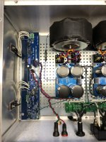
Pic is a thousand words.
All my wiring was 16 gauge.
Kept 16 gauge for +/- DC rails from Cap Bank to amp board…twisted as requested.
Connected 16 gauge ground cable from Cap Bank directly to negative output binding post.
Kept 16 gauge from amp board to positive output binding post.
Twisted the two as they allowed.
Added small 22 gauge ground wire from amp board to ground on Cap Bank.
Left input grounded with mini jumper in place.
Fired up.
Noise is at least times worse.
Sounds like transformer humming out of speaker amplified.
I’m starting to wonder if it is these Avel transformers…an audible hum comes directly from them when I fire up these amps.
Never had that issue with other builds where I used Antek or Triad.
I don’t believe they have any internal shielding like the Anteks.
But I was able to get the first one dead quiet…no idea why this one won’t behave.
😢
Attachments
When you play with the ground wire from PSU to amp, do you notice changes? I recall getting improvement when I routed my ground wire tight, parallel and behind the board.
Noise was changing when shifting +/- DC rail wires which ran twisted only partially with ground (about 1/3 distance).
Afterwards, I extended ground wire to twist the entire way to +/- connectors on amp board and then to its connector on amp board.(previous pic Ben commented on)
Noise level was reduced I think, but not gone.
Shifting wires afterwards no longer had an affect on noise level.
Do you have a pic of your amps internal wiring?
Yes they run under the base plate twisted.Can't see the AC wires but I assume that the live and neutral are tightly twisted and they run down the middle of the case.
Rotating the transformers may help.
Tried that…both directions…no dice.
When testing in the system that’s always the case. It makes noise in and out of the system…with and without a source…with and without inputs grounded.Also all of the amplifiers, preamp, and source should be plugged into the same wall outlet, and bundle all of the AC cords together.
I have a feeling that is not gonna get rid of the noise. I think its in the power supply.As a last resort, drill new holes in the back plate to locate the input and speaker connectors far away from the AC.
Only way to know is pull a channel and swap it into quiet amp?…and/or vice-versa?
Unfortunately it’s no longer in a chassis. To be honest (and as Ben says) your wiring looks good, and the fat ground wire is routed similar to how I had mine. I think the only difference was that I routed it underneath board and along the opposite edge. It was finicky, I do remember that. One minute I had noise, then a tuck behind the board took care of it.Noise was changing when shifting +/- DC rail wires which ran twisted only partially with ground (about 1/3 distance).
Afterwards, I extended ground wire to twist the entire way to +/- connectors on amp board and then to its connector on amp board.(previous pic Ben commented on)
Noise level was reduced I think, but not gone.
Shifting wires afterwards no longer had an affect on noise level.
Do you have a pic of your amps internal wiring?
I do remember that. One minute I had noise, then a tuck behind the board took care of it.
This was similar to what happened when I was playing with the DC wiring from the Cap Bank to the amp board.
I tucked the +/- twisted pair under the board and the level of noise dropped…but didn’t disappear completely as in my first amp. I just didn’t think it was a good idea to have wiring jammed in under the board.
I just routed the ground parallel and beneath the border – it seemed to minimize the loop area and quiet the noise.
have a scope?
and, previous and this amp - you have different or identical Donuts?
I mean, who knows, maybe Quasimoding Donuts could help ...... it would be great if you can find filter data for your Donuts in Quasimodo base thread .....
and, previous and this amp - you have different or identical Donuts?
I mean, who knows, maybe Quasimoding Donuts could help ...... it would be great if you can find filter data for your Donuts in Quasimodo base thread .....
Someone gave me a digital pocket scope at one point…a DSO NANO
I downloaded a manual. Might as well be in Chinese. I have no idea how to use it, or any scope for that matter.
Same exact transformers used in both amps…Avel Lindberg Y236651…
https://www.parts-express.com/Avel-Y236651-250VA-18V18V-Toroidal-Transformer-122-620
I downloaded a manual. Might as well be in Chinese. I have no idea how to use it, or any scope for that matter.
Same exact transformers used in both amps…Avel Lindberg Y236651…
https://www.parts-express.com/Avel-Y236651-250VA-18V18V-Toroidal-Transformer-122-620
tried looking in Quasimodo base thread?
don't know exactly where it is, search for it
ok, quickie, see can you find your Donuts: https://www.diyaudio.com/community/threads/quasimodo-results-only.313202/
don't know exactly where it is, search for it
ok, quickie, see can you find your Donuts: https://www.diyaudio.com/community/threads/quasimodo-results-only.313202/
Morning ZM…
Yes…I found the original Quasi thread by Mark and also the results thread
Used the DIYAudio search and found nothing on the y236651…a few other Avel, I think one Mark was using
Resorted to Google…got a few hits where the transformer is mentioned…others looking for same info…but no response with results
I will try again today
In mean time…I found a few videos I haven’t seen before about using the DSO NANO
Maybe one is “Dummy” enough for me to figure out how to take a measurement of the noise from the amp?…or maybe I can figure out how to Quasimodo the transformers myself (might be a stretch without hand holding and no Quasi board)
Anything else I should try in the mean time?
Chromenuts, did I read correctly that you are now getting mechanical noises from the transformers themselves as well? 🙁
I can't tell from the photos but I assume the CL60 thermistors are connected to PS ground.
Have you tried powering up one channel at a time (by removing the other fuse) and see if the noise changes?
I can't tell from the photos but I assume the CL60 thermistors are connected to PS ground.
Have you tried powering up one channel at a time (by removing the other fuse) and see if the noise changes?
.....
Anything else I should try in the mean time?
you can use non-scientific dummy ZM approach in this case - make quasimodo filter using more or less most common values of 10nF and 150nF caps, and varying resistor value ..... starting from 47R and going down, simply relying on your ears to spot some difference in buzz, both at spk output and from xformer itself
Ask and ye shall receive…
After fruitless manual search I posted in Quasi result thread…rhthatcher came to my rescue
https://www.diyaudio.com/community/...asimodo-test-jig.243100/page-101#post-6424902
“post 2015
18R works like a champ if you’re using independent secondaries and Cx 10nF and Cs 150nF”
Found some extra 10nF 250V WIMA film caps I ordered for Bi Amp crossovers
Desperately searching for a 150nF in my various boxes and bins…no luck so far
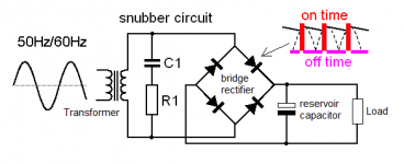
I haven’t seen the circuit of how these should be wired into the supply yet…I’m assuming it should be between the transformer and the Cap Bank?
Wondering what the resistors need to be rated to?
After fruitless manual search I posted in Quasi result thread…rhthatcher came to my rescue
https://www.diyaudio.com/community/...asimodo-test-jig.243100/page-101#post-6424902
“post 2015
18R works like a champ if you’re using independent secondaries and Cx 10nF and Cs 150nF”
Found some extra 10nF 250V WIMA film caps I ordered for Bi Amp crossovers
Desperately searching for a 150nF in my various boxes and bins…no luck so far
I haven’t seen the circuit of how these should be wired into the supply yet…I’m assuming it should be between the transformer and the Cap Bank?
Wondering what the resistors need to be rated to?
Last edited:
“Chromenuts, did I read correctly that you are now getting mechanical noises from the transformers themselves as well?”
Hi Dennis…they’ve always made a certain amount of humming noise in both amp builds.
Yes…that’s how I’ve been working
Hi Dennis…they’ve always made a certain amount of humming noise in both amp builds.
Yup they areI can't tell from the photos but I assume the CL60 thermistors are connected to PS ground.
Have you tried powering up one channel at a time (by removing the other fuse) and see if the noise changes?
Yes…that’s how I’ve been working
......
I haven’t seen the circuit of how these should be wired into the supply yet…I’m assuming it should be between the transformer and the Cap Bank?
Wondering what the resistors need to be rated to?
look no further, first or second page of data thread is having exact picture - one filter per secondary (so prior to bridges)
resistor regular 0207 size, caps 100V


post #17 https://www.diyaudio.com/community/threads/quasimodo-results-only.313202/post-5692124
Yes…that was a brain fart that was still bouncing around my head when I made a run to the only electronics store I know of in my area…about 40 min drive.
As soon as I started asking the owner about stock and was trying to convert pF, nF, uF in my head I realized my mistake.
They have limited generic mostly NTE stock…similar to old Radio Shack which are all but gone now.
Worse news…he wants out to retire. Either business sells or he closes the doors in 4 months.
I was in dispair as now there will be no emergency source anywhere nearby.
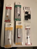
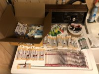
I lost my mind and started buying anything similar to what I thought I could use for snubbers and a few other things I had in mind.
Luckily, he gave me a nice discount off retail pricing.
Picture of haul and best matches to what we said should work for Quasimodo.
They are Mylar film caps. I found a few 100V electrolytic @ .1uf…and the only Polypropylene caps in the store which are 250V @ .1 uF and .22uF.
Resistors are standard metal film .5 watt 2%…so should be OK…got a whole bunch of values from 11-47 Ohm and some others since I don’t have many in the drawers.
Any issues with using Mylar for the snubbers?…hope not
As soon as I started asking the owner about stock and was trying to convert pF, nF, uF in my head I realized my mistake.
They have limited generic mostly NTE stock…similar to old Radio Shack which are all but gone now.
Worse news…he wants out to retire. Either business sells or he closes the doors in 4 months.
I was in dispair as now there will be no emergency source anywhere nearby.
I lost my mind and started buying anything similar to what I thought I could use for snubbers and a few other things I had in mind.
Luckily, he gave me a nice discount off retail pricing.
Picture of haul and best matches to what we said should work for Quasimodo.
They are Mylar film caps. I found a few 100V electrolytic @ .1uf…and the only Polypropylene caps in the store which are 250V @ .1 uF and .22uF.
Resistors are standard metal film .5 watt 2%…so should be OK…got a whole bunch of values from 11-47 Ohm and some others since I don’t have many in the drawers.
Any issues with using Mylar for the snubbers?…hope not
Attachments
Thanks ZM…even better was Mark’s Quasimodo pdf from the thread.
When I first glanced it over, I thought it was simply devoted to explaining the Quasi and testing with it.
Went back and discovered a complete explanation of the snubber circuit along with values used and placement a few pages into it.
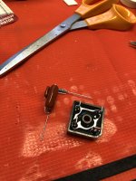
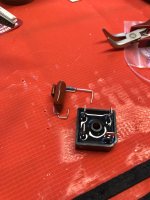
Hardest part was trying to figure out how to build and integrate it with such limited space in between the transformers and rectifiers.
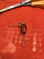
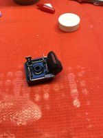
Finally got some time yesterday to pull out a pair of the bridges and add snubbers.
My daughters dance recital is today…not sure if I’ll have time to get them back in and test…
When I first glanced it over, I thought it was simply devoted to explaining the Quasi and testing with it.
Went back and discovered a complete explanation of the snubber circuit along with values used and placement a few pages into it.
Hardest part was trying to figure out how to build and integrate it with such limited space in between the transformers and rectifiers.
Finally got some time yesterday to pull out a pair of the bridges and add snubbers.
My daughters dance recital is today…not sure if I’ll have time to get them back in and test…
Attachments
- Home
- Amplifiers
- Pass Labs
- Babelfish ᄅſ....or FW J2 on Steroids .... or Not your Father's J2!