"just send them all to OPLDF"
Ok.....will first see if I can find the SJEPs 🙂 .....they where for the Skinny J2 project which has been dropped.
I had 2 x FW clone chassis which are now in Austria. I had to many boxes to fill up my home. It makes more sense to reuse chassis with PSU and everything.
Will also see if I have saved the FW F8 article where the design with current feedback is explained. I am quire sure Nelson had a short article for most FW amps telling a little bit of the design with some rough schematics just showing the concept. They were fun to read.
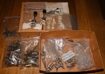
I found a box filled with very vintage (very old) Elma stuff. Maybe you can use that instead of the SJEPs 🙂
I have probably no use for it. It was from a time where you built your rotary switches from scratch. It requires that you can buy the individual contact decks (or "wafers" seems to be the name Elma use). I think today you can only buy a finished assembled rotary switch. I don't use rotary switches I switch manually at "RCA level".
Ok.....will first see if I can find the SJEPs 🙂 .....they where for the Skinny J2 project which has been dropped.
I had 2 x FW clone chassis which are now in Austria. I had to many boxes to fill up my home. It makes more sense to reuse chassis with PSU and everything.
Will also see if I have saved the FW F8 article where the design with current feedback is explained. I am quire sure Nelson had a short article for most FW amps telling a little bit of the design with some rough schematics just showing the concept. They were fun to read.
I found a box filled with very vintage (very old) Elma stuff. Maybe you can use that instead of the SJEPs 🙂
I have probably no use for it. It was from a time where you built your rotary switches from scratch. It requires that you can buy the individual contact decks (or "wafers" seems to be the name Elma use). I think today you can only buy a finished assembled rotary switch. I don't use rotary switches I switch manually at "RCA level".
Attachments
What parts are better then SJEP120R100? Really hard to believe that there are no substitutes for this SJEP. No other power JFETs cant be used in even a different modified schematic?in fact, when I better think of
SJEP120R100 are not good at all
just send them all to OPLDF
What means OPLDF? 🙄
In soundwise are the SJEP and SIT similar or how you describe them? F8 SJEP vs Babelfish XA252 SIT?
A SIT is a power JFET so it is about the curves (it can simulate a Triode tube):
https://www.firstwatt.com/product/sit-intro/
A MOSFET is more like a Pentode looking at curves.
That is the understanding I have got......
https://www.firstwatt.com/product/sit-intro/
A MOSFET is more like a Pentode looking at curves.
That is the understanding I have got......


No other power JFETs cant be used in even a different modified schematic?
of course it's possible; but, then, that's different amp
how much of proper logic is in question: "can I use VT4C in place of EL34?", as example........
F8 SJEP vs Babelfish XA252 SIT?
all my amps are sounding the same
go figure


Will leave to ZM to confirm but my guess is there is no optimum as he shows a few values in posts further down. There are various Idss listed and the corresponding resistor values to set proper Iq for output.
Seems like the combo of resistors and trim pot range will allow proper adjustment on JFet from 6-9mA.
Seems like the combo of resistors and trim pot range will allow proper adjustment on JFet from 6-9mA.
Yeh, I looked at that post, I will go for an Idss in the middle of the range ZM has given figures on.
Seems like the combo of resistors and trim pot range will allow proper adjustment on JFet from 6-9mA.
yup
name of listing game was to devise resistor-pot combo values, to cover probable Idss values
and, keeping fixed resistor fixed in value
 , while pot bypassed with cap (thus nonexisting for AC), OLG is not changing ........ resulting in more or less same performance, whatever Idss of JFet
anyhow, I'm pretty much positive that entire BL range is covered
I have ordered some boards as I found the design interesting.
Very simple and with some gain. SE (2nd harmonic dominant). Low output impedance. Low THD. Large bandwidth.
One major difference from the original F8 is the "missing" output capacitors (symmetrical PSU).
A practical question to prepare the build in my head:
What is the trick to know exactly where to bend the power transistor legs so everything fits?
I assume you mount first the two power transistors and bend the legs (90 degree or so) and then place the PBC and then solder the power transistor legs?
I have built some amps and don't recall bigger troubles with this so will probably succeed again 😎
If you look at ZM's drilling details in post #1, you will see that the distance from the FET mounting hole to the pcb lands for the legs is 20mm. So that basically means you bend the 3 legs at 90 degrees upwards at the point where the legs transition from the wider width to the narrow leg width.
I bend these first, then mount the output fets to the heatsink with M3 screws and insulator/grease. Then carefully lower the finished pcb over the 6 legs that are pointing up at you and push the pcb in place (I use 6mm nylon threaded spacers) and solder the fet leads to the lands on the front of the pcb.
Job done.
I see......thank you!
Will check my SJEPs when I find them to see if they have this "leg feature". If not I can set a little mark where to bend.
I will try not to have any mechanical stress at the power transistor solder joints when everything is mounted/soldered.
Will check my SJEPs when I find them to see if they have this "leg feature". If not I can set a little mark where to bend.
I will try not to have any mechanical stress at the power transistor solder joints when everything is mounted/soldered.
The Semisouths are the same. I hold the three legs with fine long nosed pliers at the point where the legs transition to the narrower width and I bend the legs up. That way you are not putting any stress on the legs next to the plastic fet body.
You might just have to tweak the legs slightly once the fets are bolted up to match the pcb mounting holes.
By the way, do not overtighten the fet mounting screws into the heatsink. 1 to 1.2 N/m is recommended if you have a torque driver. I do these up finger tight and once the pcb is on and soldered then I do the screws up just tight with a large diameter flat washer and spring washer..
Last edited:
Yes, I purchased the expensive Wiha ESD save torque handles. They are really nice when you have them.
I look forward to use them again. I also have the large diamenter shims to even out the presure for the power transistors.
I remember a student job I had soldering some high sensitive boards for large experiments in particle physics. There it was mandatory to cut legs first before soldering. It was done using a special cutter that took up the "chock" from the cutting. That procedure I do not follow anymore........ 😢
I do these up finger tight and once the pcb is on and soldered then I do the screws up just tight with a large diameter flat washer and spring washer..
torque prior to soldering
not exactly particle physics, but pin particles are happier that way
for convenience, use appropriately sized adjustable wrench
for mica & goop, torque scwdrvr is not so important, while for Keratherm and Alumina pads, it is

- Home
- Amplifiers
- Pass Labs
- Babelfish F8