B1 BUFFER
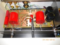
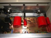
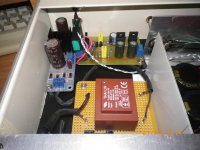
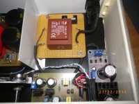
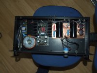
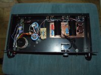
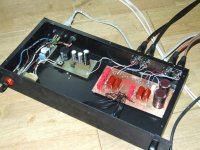
Beside-Inside.
The transformer 2X12V 0.130A per rail
The ripple about PSU after JLH shunt at 22V is 50-100μV
Next day i will show the foto 50-100μV.
Beside-Inside.
The transformer 2X12V 0.130A per rail
The ripple about PSU after JLH shunt at 22V is 50-100μV
Next day i will show the foto 50-100μV.
Attachments
Last edited:
the Signal connection is a two wire arrangement.
If you include a large loop area in that two wire connection you make the input susceptible to interference.
Think of the relay as a single pole switch.
The return runs past the single pole switch as close as possible to minimise that loop area.
Now look at the input of the receiver circuit.
It expects a two wire connection.
You must feed it a two wire connection from your selector board.
Thanks AndrewT!
Continuation from here
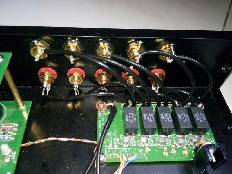
Recently I purchased some shielded wire and redone the signal wiring with additional ground path along each one. Please see below.
Outside with some engraving -
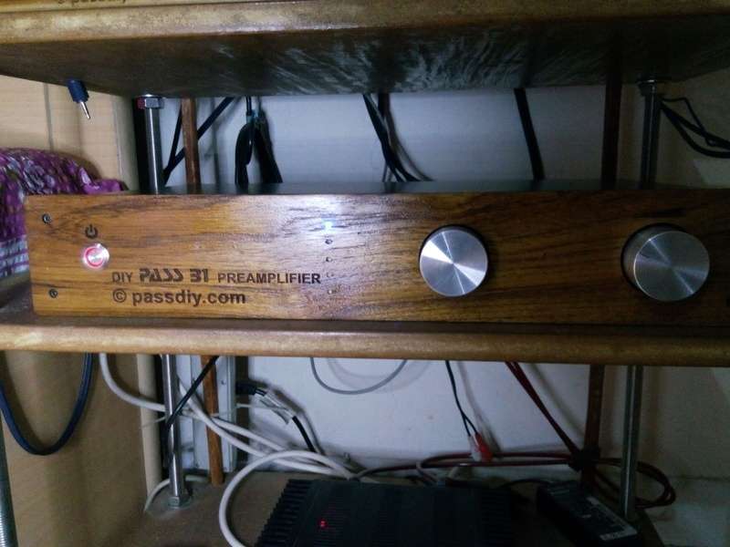
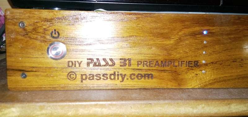
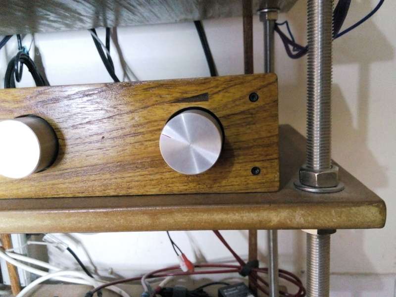
Andrew T, yes and no. It's the SALAS reg part of the DCB1 with the B1 part removed driving the original B1.
I did build the DCB1 but it had problems because of my home-brew PCB so I chopped that part of the PCB and just used the reg. The B1 then allowed me to use the exotic PIOs that you can see on the B1 PCB.
I did build the DCB1 but it had problems because of my home-brew PCB so I chopped that part of the PCB and just used the reg. The B1 then allowed me to use the exotic PIOs that you can see on the B1 PCB.
It really doesn't need them to be twisted it is absolutely silent with no cross talk whatsoever.
When you consider that the Pass B1 uses a Wallmart Brick it's quite amusing to see what some people will do.
I could only hear a minor difference between the LM317 PSU that I originally employed. I certainly couldn't hear any difference at all by upping the SALAS shunt current above the 180mA that is standard with Salas' original design.
I could only hear a minor difference between the LM317 PSU that I originally employed. I certainly couldn't hear any difference at all by upping the SALAS shunt current above the 180mA that is standard with Salas' original design.
Attachments
Andrew T, yes and no. It's the SALAS reg part of the DCB1 with the B1 part removed driving the original B1.
I did build the DCB1 but it had problems because of my home-brew PCB so I chopped that part of the PCB and just used the reg. The B1 then allowed me to use the exotic PIOs that you can see on the B1 PCB.
Or put a hacksaw to an mezmerise pcb... 6 inputs 🙂
Regards
I only needed two inputs which the B1 can cater for. But yes, you can just run a hacksaw through the mesmerize to separate the PSU.
Did you measure the output hum + noise before and after the input wiring change?
Actually No! I did not measure anything. Its silent as usual. I am using r-core transformer with LM317 based regulator + LCL filter. But now its mental satisfaction after doing this rewiring that I have everything correct.
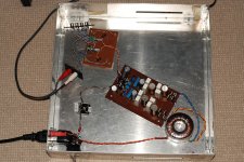
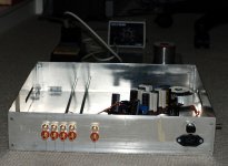
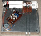
Since it is getting close to finished I decided I would upload a picture of my work in progress.
It is basically a DCB1 based on the Salas circuit but only the B1 part (with 270K resistors on the output). I used my own LM317 (YARPS) power supply. The B1 is made on Verro borad as can be seen in the picture.
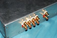
I still need to put in the output wiring and wire up to rca jacks. It has a 20K "stepped attenuator ($10 HK job) and a cheapo double pole 4 position switch for four inputs.
This is basically a temporary build to give me something to allow input switching until such time as I get my synergy crossover (which uses a number of B1's) sorted. I got sick of not having a preamp!
Tony.
Attachments
We I have the B1 working. It is not "finished" as yet. but it plays music 🙂
I must say I am very happy with the result. I have not had clear and clean reproduction of CD's via my marantz DV-18 for probably close on 10 years now. It seemed to be an interaction problem between the player and the preamp in my amp, which caused distortion.
No such problem using the B1 and feeding the amp direct from it 😀 It is also a nice step up from what I have been using, which is the onboard sound of my HTPC!
Ultimate test was playing white stripes. It sounded good for the first time in a very long time! Black Math still is a bit on the harsh side but a LOT better! 🙂
Attached is the picture of the prototype chassis that my father in law made up for me. I will probably end up buying a commercial case. I've ordered some nice RCA jacks, and I need to make some extensions for the pot and switch. But the important thing is that it has removed nastiness from my system that has been bugging me for years! I should have made it much sooner. I've had the fets since Oct 2009 🙄
Tony.
Attachments
Hi Nikosokey,
What artwork did you use to etch your B1 pcb? I was hoping to try etching one, thanks.
What artwork did you use to etch your B1 pcb? I was hoping to try etching one, thanks.
@hartbigsky this Mezmerize B1 Buffer Preamp (Makes 2 channels; Rev 1.0) - Circuit Boards is one option 🙂
Tony.
Tony.
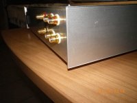
OK I decided that it is close enough to finished to post a "final" set of photos. I only really need to attach the feet to the case and fasten the lid on properly. As I said before this case was a prototype my Father in law knocked up for sizing purposes, It wasn't originally intended to be used to house anything. But since I had it I decided it was good to practice on 🙂
The Final version (as I see it in my head) will have six inputs all relay switched (latching types controlled by momentary push button) and my Synergy active crossover. I will probably have a passive only switching board (with the relays) and separate board with all active circuitry on it. I worry about ground issues if I have more than one active board in the same chassis.
This initial B1 will do me nicely till I get a board layout done for the synergy and input switching circuitry, which based on my snails pace will be a while.
Just want to say thanks to Nelson for the original design, and thanks to Salas for the DCB1 version. I finally have a preamp of excellent quality!
No measurements as yet. I'll post some once I have a balanced to unbalanced converter up and running, as I will need that I think to do the measurements justice (due to my sound cards poor performance when running the balanced output to an unbalanced component.
Tony.
Attachments
Last edited:
- Home
- Amplifiers
- Pass Labs
- B1 preamp build thread
