I think you are talking about the diyAudio PSU board -- Yes, technically it will, but it's complete overkill, and there is no preregulation, so there is not a compelling reason to use it. That PCB is really made for poweamps and things that need bi-polar PSU.
However, if you using the PassDIY B1 board, just use a wall-wart. It was designed to use a wall wart and sounds great with it. If you want to change it later, feel free to do something more complicated.
If you are dying to have a regulated supply on it from the beginning, try this - LV-Regulator
However, if you using the PassDIY B1 board, just use a wall-wart. It was designed to use a wall wart and sounds great with it. If you want to change it later, feel free to do something more complicated.
If you are dying to have a regulated supply on it from the beginning, try this - LV-Regulator
I recently completed two pass B1 preamps - 1. for my son and 2 for me. Both are paired with ACAmp and I plan to use F5 turbo v2 with it. Both have 5-1 source stereo selector.
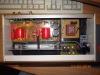
This is for my son which is using LM317 based regulated PS powered by 22-0-22 rcore transformer. Also I have used +15,0,-15 supply for external phono preamp etc. Here I am using resistive ladder 23 step volume control of 47KΩ.


Another one is for my listening room. Ths is double buffer B1-> (Volume Control) -> B1. This is also using LM317 based regulated PS powered by 22-0-22 rcore transformer. Here I took out unregulated +33V, 0, -33V for Pearl 2 Phono stage. Volume Controls is LDR based Attenuator.


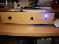
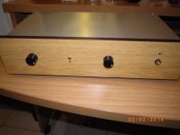
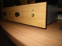
In the rack both look same from outside, hence posting only one.

I find it sounds more lively with double buffer, one before volume control and one after volume control.
This is for my son which is using LM317 based regulated PS powered by 22-0-22 rcore transformer. Also I have used +15,0,-15 supply for external phono preamp etc. Here I am using resistive ladder 23 step volume control of 47KΩ.
Another one is for my listening room. Ths is double buffer B1-> (Volume Control) -> B1. This is also using LM317 based regulated PS powered by 22-0-22 rcore transformer. Here I took out unregulated +33V, 0, -33V for Pearl 2 Phono stage. Volume Controls is LDR based Attenuator.
In the rack both look same from outside, hence posting only one.
I find it sounds more lively with double buffer, one before volume control and one after volume control.
Last edited:

I am using the same Power supply designed by Omishra for B1,SSP and CNC Phonostage.It is one of the best available Power supply for preamps,and also has adjustable output voltage.
Regards,
Sachin
Regards,
Sachin
Last edited:
I like the layout putting the input selector relays beside the Input sockets.
But you have incorporated enormous loop area into every input.
The Signal to the relay is a TWO wire connection. The Flow and the Return. You must run the Flow and Return TOGETHER to each Relay. The Return bypasses the relay and then follows the relay output to the Receiver, or coax than then feeds the receiver.
Each single Wire Flow from your input sockets must have it's partner Return Wire close coupled or even better a twisted pair.
You have 5 stereo inputs. That requires 10 twisted pairs.
Last edited:
Pass DIY Addict
Joined 2000
Paid Member
Sachin - do you have a link for Omishra's power supply? Geez, I don't pay attention for a little while and feel left behind when I return...
Thanks!
Thanks!
Sachin - do you have a link for Omishra's power supply? Geez, I don't pay attention for a little while and feel left behind when I return...
Thanks!
You can see few OPS pics here Introducing the (mini) Tower of Power - AudioKarma.org Home Audio Stereo Discussion Forums
and here Looking for full size Chassis for CNC phono pre - AudioKarma.org Home Audio Stereo Discussion Forums
Regards,
Sachin
Sachin - do you have a link for Omishra's power supply? Geez, I don't pay attention for a little while and feel left behind when I return...
Thanks!
This is here! It has link to schematic and PCB as well.
Thanks for suggestion!I like the layout putting the input selector relays beside the Input sockets.
But you have incorporated enormous loop area into every input.
The Signal to the relay is a TWO wire connection. The Flow and the Return. You must run the Flow and Return TOGETHER to each Relay. The Return bypasses the relay and then follows the relay output to the Receiver, or coax than then feeds the receiver.
Each single Wire Flow from your input sockets must have it's partner Return Wire close coupled or even better a twisted pair.
You have 5 stereo inputs. That requires 10 twisted pairs.
I thought this does not have any gain stage. So I can use bare wires for connection without shield and twisting. There is return path of all RCAs connected together and referenced at ground pin of PS capacitor of B1. Relay switches only live wire of stereo, L and R simultaneously. Do you think it's still problem? It's dead quite and sounding lively as always.
the Signal connection is a two wire arrangement.
If you include a large loop area in that two wire connection you make the input susceptible to interference.
Think of the relay as a single pole switch.
The return runs past the single pole switch as close as possible to minimise that loop area.
Now look at the input of the receiver circuit.
It expects a two wire connection.
You must feed it a two wire connection from your selector board.
Hi 6L6,
I am trying to figure out my input and attenuator connections. I see a jumper on the input switch location R1/L1 to center through hole in photos. Do I use for a 2 input selector switch and it is bypassed for multi selector? Also CCW-W-CW I assume is volume so stepped atten. has in/out on each stack so How do you hook up? Thanks for your help!
I am trying to figure out my input and attenuator connections. I see a jumper on the input switch location R1/L1 to center through hole in photos. Do I use for a 2 input selector switch and it is bypassed for multi selector? Also CCW-W-CW I assume is volume so stepped atten. has in/out on each stack so How do you hook up? Thanks for your help!
B1 BUFFER
Hi
this is my B1 Buffer .
Pcb its from gerber fille .
2sk 170 matched to 7.8 ma at 640 mv vgs
10mf-1mf Audiophiller
JLH Shunt Reg at 22V
LM 317 at 22.10 V
Two separate pots 25kΩ
Hi
this is my B1 Buffer .
Pcb its from gerber fille .
2sk 170 matched to 7.8 ma at 640 mv vgs
10mf-1mf Audiophiller
JLH Shunt Reg at 22V
LM 317 at 22.10 V
Two separate pots 25kΩ
Attachments
I am trying to figure out my input and attenuator connections. I see a jumper on the input switch location R1/L1 to center through hole in photos. Do I use for a 2 input selector switch and it is bypassed for multi selector?
If you only want 2 sources, then use a DPDT switch and connect to the PCB. If you want to use a rotary for 3 or more sources, connect to one set of inputs on the board, jumper the PCB switch connections and switch everything with the rotary.
Also CCW-W-CW I assume is volume so stepped atten. has in/out on each stack so How do you hook up? Thanks for your help!
CCW is ground, CW is in, W is out. ( I think...)
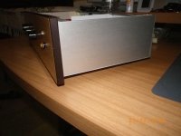
Is there a reference to the source for the chassis? It would be fantastic to have that. I've been struggling trying to figure out a case situation for my B1.
LoL! *)
Seriously, I am interested in where others had their cases made. I've considered using the case for the ACA but I don't think you can get it un-drilled, and besides its not a very good looking preamp case. I'd like something more horizontal.
Seriously, I am interested in where others had their cases made. I've considered using the case for the ACA but I don't think you can get it un-drilled, and besides its not a very good looking preamp case. I'd like something more horizontal.
Also, do you have a list of materials for the Power Supply? That is a nifty small form-factor transformer you are using. Is the reset of the PS the regular design everyone else has been more or less using?
- Home
- Amplifiers
- Pass Labs
- B1 preamp build thread