But with a p and n channel jfet it would become a push pull buffer, isn't it?
I'm considering this SE version.
I'm considering this SE version.
any drawback in building a dual supplied version?
Not really, but what is the point?
Some people are obsessed with bipolar supplies and no caps in the signal path, especially electro ones.
I am not one of them.
I like the simplicity of single polarity PSUs for amps and preamps. To me they are easy to understand, easy to implement, logical.
If you like they are more Zen than the bipolar versions.
If tube circuits historically use single polarity supplies and we all rave about their sound quality, there is no reason why we should not use the same approach to transistor circuits.
Single ended amplification is simplicity in itself so why complicate things?
Maybe build both versions and listen, then you can decide for yourself.
Thanks for your feedback, the answer to your two questions is in the part you deleted when quoting me: I would use this buffer in a rack system that already has a stabilized dual supply. On top of that, having many I/Os, no coupling caps would mean a cheaper system as well.Not really, but what is the point?
Single ended amplification is simplicity in itself so why complicate things?
You can also use two n-ch jfets in a bipolar supply, but there is likely to be >some< DC, according to Borbely (see 'JFets the new frontier' parts 1 & 2).
Not so expensive and perfect fit :
1µF Mouser 667-ECW-FE2W105KA
10µF Mouser 667-EZP-E63106LTB
🙂
Damien
1µF Mouser 667-ECW-FE2W105KA
10µF Mouser 667-EZP-E63106LTB
🙂
Damien
Thanks for your feedback, the answer to your two questions is in the part you deleted when quoting me: I would use this buffer in a rack system that already has a stabilized dual supply. On top of that, having many I/Os, no coupling caps would mean a cheaper system as well.
Well, there you go.
You answered your previous question nicely...
You obviously already made the decision to use bipolar supplies, so my previous rumblings were redundant.
Thanks Andersonix, I will read those threads tonight.
Thanks Stanislav, no decisions made yet, just an opportunity and I asked to you more experienced people about this circuit if that application could have been possible.
Andersonix raised a good point indeed.
Thanks Stanislav, no decisions made yet, just an opportunity and I asked to you more experienced people about this circuit if that application could have been possible.
Andersonix raised a good point indeed.
If anyone is prepared to give me a hint about where and what to measure I would be most grateful. I have access to scope and multimeter, as well as a lab power supply.
what power supply voltage do you have? 18V?
between the point R2 and R3 (10k) and ground halve of the psu volts (9V)?
does the led (D2) light up?
between the point R2 and R3 (10k) and ground halve of the psu volts (9V)?
does the led (D2) light up?
I am running 19,5 volts right now, but have tried with other levels to. Will control measure as suggested. D2 lights up just fine.
Interesting
Voltage is right on.
I would like to see the input level.
The volume pot wiring.
My first guess is overdrive.
DB in MN
Voltage is right on.
I would like to see the input level.
The volume pot wiring.
My first guess is overdrive.
DB in MN
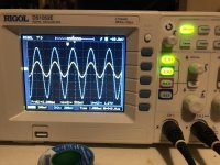
I guess the 1.27Vpp is output of the ACA. The negative signal is noticeably greater than the positive part. It would be a significant amount of 2nd order harmonic. When you say the sound is terrible, how would you describe it?
Hi - no the 1,27 volts is the output from the B1 - the yellow signal is generated by my computer and measured at the input to the B1.
Sound is clearly distorted, overdrive is not unlikely. Not "sweet and creamy", rather sharp and not agreeable. I agree on the difference between pos and neg. I will do some new measures tonight and post them - anything in particular I should focus on?
Sound is clearly distorted, overdrive is not unlikely. Not "sweet and creamy", rather sharp and not agreeable. I agree on the difference between pos and neg. I will do some new measures tonight and post them - anything in particular I should focus on?
I did some new measures - no DC on output. Also did some new sine measures with the scope. Everything looks fine until I measure after the JFets - then the negativ sving differs from the positive. When I measure the DCvoltage across the JFets Q100 and Q200, I noticed something strange: the gate has 1/2 the supply voltage as expected, but the source is the same as the supply - isn't the source supposed to be half the supply?
- Home
- Amplifiers
- Pass Labs
- B1 Buffer Preamp