My watch stopped working. But it is 100% accurate twice a day. If I can just get enough broken watches there will always be an accurate one.
My watch stopped working. But it is 100% accurate twice a day. If I can just get enough broken watches there will always be an accurate one.
Brilliant!
Hi Ian,
Promising results! if the effect is cumulative, can two reclockpi be used in a row?
Limited by the MCLK jitter, I don't think more ReClockPi can make any difference.
Using one would be good enough. That's my suggestion.
Regards,
Ian
Too many syllables for I, so had to shortened to RCP. It's like saying WiFiFi. RePi works too.
Because of the amazing flexibility of Ian's LiFePO4 MKIII and I'm like totally bored of the Raspberry Pi, I want to try something different for desktop. So for the 13.2V rail, instead of utilising that rail for 6.6V to LinearPi to UCConditioner 5V to power an RPi I want to see if I can go 13.2V first to a motherboard.
I remember Google and Microsoft use 12V battery-powered motherboards for their datacentres. I'm trying to do the same for desktop audio.
Initially, I wanted a 12V endpoint like a NUC but the trend seems to be high-power CPU music servers these days and not endpoints anymore. So I'm skipping the endpoint step altogether along with skipping the RPi.
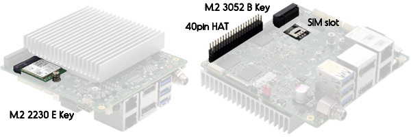
I also wanted to try 12V UP Boards, but their 40-pin GPIO is proprietary software not open so hard pass. I wanted to try to extract I2S from UP Board straight into the Q3 (bypassing a USB to I2S adapter conversion) via Windows or Ubuntu, but really need Arch Linux for the realtime kernel low latency ramroot which UP Board does not support.
Financially, the UP Board kind of makes sense. To go BridgePi + Combo384, it's about $130. For another $130, you can get an UP Board. It's just the HAT is unproven and closed off SW-wise. It might tho work well as they are constantly releasing new products thus improved GPIO software. It's just there's no sample size yet for audio HAT. You can even theoretically attach a Q3 on top of the UP Board, but cleaner to separate power.

I decided not to cancel my 12V motherboard, so we will see what happens. I like to see what the StationPi Pro offers, but if I go 12V I go raw thus server only, no add-ons so my SuperCaps go to waste.
Because of the amazing flexibility of Ian's LiFePO4 MKIII and I'm like totally bored of the Raspberry Pi, I want to try something different for desktop. So for the 13.2V rail, instead of utilising that rail for 6.6V to LinearPi to UCConditioner 5V to power an RPi I want to see if I can go 13.2V first to a motherboard.
I remember Google and Microsoft use 12V battery-powered motherboards for their datacentres. I'm trying to do the same for desktop audio.
Initially, I wanted a 12V endpoint like a NUC but the trend seems to be high-power CPU music servers these days and not endpoints anymore. So I'm skipping the endpoint step altogether along with skipping the RPi.
I also wanted to try 12V UP Boards, but their 40-pin GPIO is proprietary software not open so hard pass. I wanted to try to extract I2S from UP Board straight into the Q3 (bypassing a USB to I2S adapter conversion) via Windows or Ubuntu, but really need Arch Linux for the realtime kernel low latency ramroot which UP Board does not support.
Financially, the UP Board kind of makes sense. To go BridgePi + Combo384, it's about $130. For another $130, you can get an UP Board. It's just the HAT is unproven and closed off SW-wise. It might tho work well as they are constantly releasing new products thus improved GPIO software. It's just there's no sample size yet for audio HAT. You can even theoretically attach a Q3 on top of the UP Board, but cleaner to separate power.
I decided not to cancel my 12V motherboard, so we will see what happens. I like to see what the StationPi Pro offers, but if I go 12V I go raw thus server only, no add-ons so my SuperCaps go to waste.
Last edited:
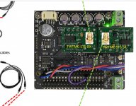
ReClockPi SCK signal quality and measurement
Please find the attached measurement results of ReClockPi SCK signal quality
1.RcClockPi SCK waveform
Same as RcClockPi LRCK, the SCK signal is almost as an ideal square wave. Rising/falling time only 0.9ns. Rising/Falling edges are super clean. No any ripples on both high and low logic levels. That ensures the lowest possible EMI noise will be transferred into the DAC along with the LRCK signal. It’s the newly designed discrete logic circuits that results in this low noise re-clock performance.
2.ReClockPi SCK time jitter
ReClockPi SCK time jitter was also reduced to a best possible level when upgrading a FifoPi with a ReClockPi.
When playing a 88.2KHz music, the FifoPi Q3's 5.6448MHz SCK signal RMS jitter was 6.78 ps. After a ReClockPi was installed, the same 5.6448 MHz SCK signal RMS jitter had been reduced to 3.76 ps. That’s a very big improvement. It would be great news for those DACs that rely on SCK for the performance, such as ESS DACs, TDA1541 DACs, DDDAC and many others.
3.Calculated phase noise plot.
When converting the RMS jitter into phase noise, the SCK phase noise plot was also very promising. Though in the real world, it’s impossible to get -6dB improvement at each time divided by 2, but this calculated RcClockPi 5.6448 MHz SCK phase noise plot could be the best SCK phase noise I have ever seen. Down the road, when replacing the CCHD957 with a better XO or OCXO, there will be still more room for new improvement. Please note that the integration bandwidth was wide from 0.1Hz to 1MHz.
Testing conditions:
Lecroy LC584AXL 1GHz oscilloscope with jttter measurement package.
8GS/s sampling
1GHz Global bandwidth
50 ohm coaxial cable DC coupling
0.1us/div time base
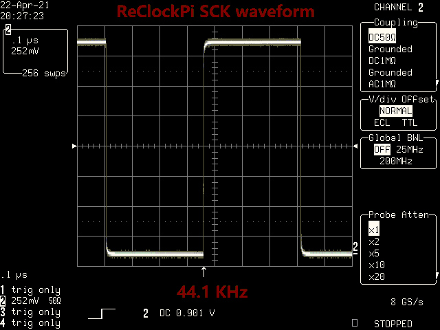
Sck44.1WaveformAfterReClockPi by Ian, on Flickr

Sck88JitterBeforeAfterReClockPi by Ian, on Flickr
 SCKphaseNoise by Ian, on Flickr
Ian
Please find the attached measurement results of ReClockPi SCK signal quality
1.RcClockPi SCK waveform
Same as RcClockPi LRCK, the SCK signal is almost as an ideal square wave. Rising/falling time only 0.9ns. Rising/Falling edges are super clean. No any ripples on both high and low logic levels. That ensures the lowest possible EMI noise will be transferred into the DAC along with the LRCK signal. It’s the newly designed discrete logic circuits that results in this low noise re-clock performance.
2.ReClockPi SCK time jitter
ReClockPi SCK time jitter was also reduced to a best possible level when upgrading a FifoPi with a ReClockPi.
When playing a 88.2KHz music, the FifoPi Q3's 5.6448MHz SCK signal RMS jitter was 6.78 ps. After a ReClockPi was installed, the same 5.6448 MHz SCK signal RMS jitter had been reduced to 3.76 ps. That’s a very big improvement. It would be great news for those DACs that rely on SCK for the performance, such as ESS DACs, TDA1541 DACs, DDDAC and many others.
3.Calculated phase noise plot.
When converting the RMS jitter into phase noise, the SCK phase noise plot was also very promising. Though in the real world, it’s impossible to get -6dB improvement at each time divided by 2, but this calculated RcClockPi 5.6448 MHz SCK phase noise plot could be the best SCK phase noise I have ever seen. Down the road, when replacing the CCHD957 with a better XO or OCXO, there will be still more room for new improvement. Please note that the integration bandwidth was wide from 0.1Hz to 1MHz.
Testing conditions:
Lecroy LC584AXL 1GHz oscilloscope with jttter measurement package.
8GS/s sampling
1GHz Global bandwidth
50 ohm coaxial cable DC coupling
0.1us/div time base
Sck44.1WaveformAfterReClockPi by Ian, on Flickr
Sck88JitterBeforeAfterReClockPi by Ian, on Flickr
SCKphaseNoise by Ian, on FlickrIan
Last edited:
Can you do the same for BCK Ian? For the DDDAC that is the important one, not LRCK
@ddddac
Please see the above post for the RcClockPi SCK (BCK) signal quality that your are interested in.
https://www.diyaudio.com/forums/dig...mate-weapon-fight-jitter-631.html#post6631724
Good weekend.
Ian
RE EMI- The fast transitions on the clock and data lines are notorious EMI/RFI sources. Many chip vendors slow them down to have less radiation. The relatively low frequency and fast transition will have a really wide bandwidth of noise with spuria at every harmonic. Careful layout and line termination helps as does really good shielding.
Does the LeCroy extract the spectrum for the phase noise analysis? Its really impressive for an 8 bit scope to be able to read noise down to -170 dB. If that's possible I should be able to find a similar package for my Tek DSA8200.
Does the LeCroy extract the spectrum for the phase noise analysis? Its really impressive for an 8 bit scope to be able to read noise down to -170 dB. If that's possible I should be able to find a similar package for my Tek DSA8200.
@A123, so you are going to start on a high power, battery powered board, with low latency and added fifo buffer? You'll excuse me if I say that chain contains a lot of contradictions.
@ddddac
Please see the above post for the RcClockPi SCK (BCK) signal quality that your are interested in.
https://www.diyaudio.com/forums/dig...mate-weapon-fight-jitter-631.html#post6631724
Good weekend.
Ian
Thanks Ian, the results (half jitter) is even better than on LRCK I see.
looks promising.
as you made a discrete setup, what is the output drive capability of the I2S signals? in mA? and what is the typical impedance they like to see? What is the output impedance? The latter question to get a feel of the of what capacitive load of the SCK (BCK) will do. Or could you just load it with 10, 50, 100, 200pF and show the square wave?
thanks, nice work Ian
I still don't get how you extracted the phase noise data...
I always thinked that was impossible extract phase noise from jitter...
Can you please understand what I am missing ?
I always thinked that was impossible extract phase noise from jitter...
Can you please understand what I am missing ?
Hello,
Still using Aurender with wave IO '' vintage style '' and a DDDAC I mean before you received, installed and burn in your latest board a new prototype already pops up.
Almost looks like i phone sales strategy.
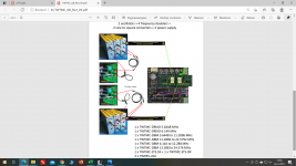
So i wanna go for Roon Nucleus and a pile of circuits.
I will go for what seems to be state of the art clock circuitry as posted in the attachment.
Can i physically combine the latest reclock pi board and still mount the two tiny boards from Andrea. Or do i need to adjust some mounting hardware?
Will i need the so called '' mini circuit transformers kits '' from Andrea? Do they provide galvanic separation?
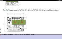
Will i need a TWTMC STS FSDO F or S board if i will use the
IAN CANADA FIFOPI Q3 ULTIMATE FIFO Reclocker Module PCM 32bit 768kHz DSD1024 DoP ?
Greetings, eduard
Still using Aurender with wave IO '' vintage style '' and a DDDAC I mean before you received, installed and burn in your latest board a new prototype already pops up.
Almost looks like i phone sales strategy.
So i wanna go for Roon Nucleus and a pile of circuits.
I will go for what seems to be state of the art clock circuitry as posted in the attachment.
Can i physically combine the latest reclock pi board and still mount the two tiny boards from Andrea. Or do i need to adjust some mounting hardware?
Will i need the so called '' mini circuit transformers kits '' from Andrea? Do they provide galvanic separation?
Will i need a TWTMC STS FSDO F or S board if i will use the
IAN CANADA FIFOPI Q3 ULTIMATE FIFO Reclocker Module PCM 32bit 768kHz DSD1024 DoP ?
Greetings, eduard
Attachments
@eduard
If the two SAM connectors are the only tall components, then I don't think there is any problem to install the two adapter PCBs under ReClockPi.
Regards,
Ian
If the two SAM connectors are the only tall components, then I don't think there is any problem to install the two adapter PCBs under ReClockPi.
Regards,
Ian
Thanks Ian, the results (half jitter) is even better than on LRCK I see.
looks promising.
as you made a discrete setup, what is the output drive capability of the I2S signals? in mA? and what is the typical impedance they like to see? What is the output impedance? The latter question to get a feel of the of what capacitive load of the SCK (BCK) will do. Or could you just load it with 10, 50, 100, 200pF and show the square wave?
thanks, nice work Ian
@dddac
The output drivers are capable for +-50mA output current. They were carefully turned to have 50 ohm output impedance. The waveform I posted was measured at 50 ohm load with 11pF capacitance. The Tr and Tf were 0.9ns measured . When increase the load capacitance to 50pF, both Tr and Tf will be increase but no great than 2.5ns.
Please let me know if you need more information.
Regards,
Ian
@eduard
If the two SAM connectors are the only tall components, then I don't think there is any problem to install the two adapter PCBs under ReClockPi.
Regards,
Ian
Hello Ian,
I think it is only the two SAM which are tall. Andrea can surely confirm and the best location for the ReClockPi is indeed the one '' covering '' the circuit underneath?
Greetings, Eduard
I still don't get how you extracted the phase noise data...
I always thinked that was impossible extract phase noise from jitter...
Can you please understand what I am missing ?
@gionag
Basically, phase jitter is the integration of the phase noise plot. Phase jitter equals to time jitter when integrating over the whole bandwidth. Phase noise and jitter can be translated in between.
https://www.eetimes.com/phase-noise-and-jitter-a-primer-for-digital-designers/
RcClockPi SCK was re-clocked by MCLK, so it's phase noise tendency will mainly follow the MCLK. To estimate the phase noise from the jitter, we need to shift the MCLK phase noise plot until the integration result equals to the RMS jitter. Have to use the integration bandwidth as wide as possible to make the result more accurate (I use 0.1Hz to 1MHz). The estimated phase noise floor could be better than a real phase noise analyzer because the phase noise calculator doesn't have a physical input noise floor limitation. However the close-in phase noise estimated result will be more accurate because the close-in phase noise weights much higher than the noise floor to the final phase jitter result.
Regards,
Ian
Last edited:
RE EMI- The fast transitions on the clock and data lines are notorious EMI/RFI sources. Many chip vendors slow them down to have less radiation...
John Westlake pointed out that sometimes using 100-ohm series termination resistors at the source end makes for better dac sound quality as compared to trying for a more exact impedance match using, say for example, 33-ohms.
He's probably not the first one to figure that out. Wadia was using that same trick years ago.
- Home
- Source & Line
- Digital Line Level
- Asynchronous I2S FIFO project, an ultimate weapon to fight the jitter