Guys, I have not seen the position and size of those resistor arrays, but what you might find helpful is if you cannot solder the regular way, what sometimes works is to apply solder paste to the pads (very thin layer) and than heat up with hot air, while you are holding resistor pressed from above. If you do not have SMD workstation, you could use heat gun, if it is the one with temperature adjustment. Obviously SMD station will be better, but if you do not have it, heat gun will do the job. You have to be careful not to apply too much of the paste, so the trick is to apply paste and takeaway with cotton swab. What is left is quite enough.
OK, I just checked picture. What you have to have is really fine braided wick. So even if your solder connects resistor legs, do not worry, you will take it easily with wick. But the key is to have the finest wick, and if you are using solder use the thinnest one you could find.
Si570 interest list:
1. bigpandahk
2. tagheuer
3. hochopeper
4. qusp (of course)
5. AR2 - definitely!
6. wktk_smile
7. hirez69
8. CeeVee - you bet!
9. number9
10. analog_sa - GB maniac
11. edbk
12. atom6422
13. misterrogers - Of Course!
14. NicMac - as usual!
15. Zoran
16. PET-240
17. Coolhead
18. Slartibartfasst
19. SYklab
20. Regland
21. Neb001
22. SPWONG
23. Greg Stewart (also of course!)
24. Vitalica
Guys, I have not seen the position and size of those resistor arrays, but what you might find helpful is if you cannot solder the regular way, what sometimes works is to apply solder paste to the pads (very thin layer) and than heat up with hot air, while you are holding resistor pressed from above. If you do not have SMD workstation, you could use heat gun, if it is the one with temperature adjustment. Obviously SMD station will be better, but if you do not have it, heat gun will do the job. You have to be careful not to apply too much of the paste, so the trick is to apply paste and takeaway with cotton swab. What is left is quite enough.
Thanks guys, you make a lot of sense on SMT soldering skills.
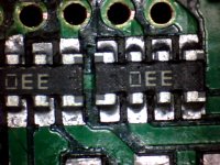
I'd like to share the way I solder the resistor array, may not the best way, but it works.
1. Heat the pads by hot air to roughly 80C, plate very thin solder to each pad by iron with needle head, I use 0.4mm solder wire.
2. File the pads having thick solder by a small fine file or sand paper and making them flat, clean left metal powder completely by PCB wash cleaner or alcohol.
3. Place flux (clean free prefer) on both the pads and the resistor array.
4. Heat the pads by hot air from SMT solder station till the solder on the pads get melt, meanwhile, pick up the resistor array on the long side with a tweezers, place the resistor array accurately over the footprint with solder melting. Remove hot air but don't move the tweezers to keep the resistor array at the position till the solder curdle. (have to wear glove on the hand holding tweezers, avoid un-stable hand under hot air)
5. Place a bit flux on the pins of the resistor array which is already on the pads, heat it by hot air from the SMT station again and making the solder melt on each pads, the tension of the melt solder from each pad will draw the resistor array into the center balanced position. Use the pin of the tweezers touch a little bit if not exactly at the center, remove hot air
6. Clean PCB again and make sure no any short or disconnect on each pin by a multi-meter.
7. Cross your fingers🙂.
Ian
Very detailed procedures, Thanks Ian.
But I have un-stable hand even under cool air😀
Me too 😀. But try to find some support under your hand, that helps.
Ian
I haven't tried this for soldering before, but when I was doing a lot of photography a while back I found I could reduce camera shake by keeping both elbows closer to my sides rather than up in the air away from my body ... just a thought.
EDIT: apologies for any embarassement if you're now sitting there waving your elbows like a chicken working this out 😉 I'm hoping nobody noticed my sitting at my desk eating lunch and doing exactly that just now!
EDIT: apologies for any embarassement if you're now sitting there waving your elbows like a chicken working this out 😉 I'm hoping nobody noticed my sitting at my desk eating lunch and doing exactly that just now!
Last edited:
Isolation board
Ian,
which is the max input voltage for the Dual XO board (J5 connector)?
Thanks
hirez69
Ian,
which is the max input voltage for the Dual XO board (J5 connector)?
Thanks
hirez69
hirez69:
The max input DC is rated at 5.5V. Could go a bit higher based on real testing, because of output current is much lower then 200ma for each LDO. But not recommend higher than 6.5V
Ian
The max input DC is rated at 5.5V. Could go a bit higher based on real testing, because of output current is much lower then 200ma for each LDO. But not recommend higher than 6.5V
Ian
Battery PCB shipped
All passive battery manage board PCB posted today for evaluation. Hope testing group will get them soon.
bigpandahk: Just sent a new isolator PCB together, four resistor arrays assembled. Hope it works.
ryanj: still not get your shipping address. Please send me an email, or let me know if your don't need the PCB.
Ian
All passive battery manage board PCB posted today for evaluation. Hope testing group will get them soon.
bigpandahk: Just sent a new isolator PCB together, four resistor arrays assembled. Hope it works.
Ian
Ian
You are GREAT. THANKS VERY MUCH.
I am still trying hard to assemble the resistor arrays correctly.😛
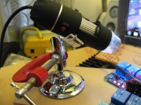
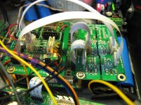
Followed Ian's procedures and with the help of microscope, I finally soldered the resistor arrays without any short. The isolator board is working now and sound GREAT.
With the board, I can clearly hear a much better bass. Will report again after run-in.
With the board, I can clearly hear a much better bass. Will report again after run-in.
Attachments
hirez69:
The max input DC is rated at 5.5V. Could go a bit higher based on real testing, because of output current is much lower then 200ma for each LDO. But not recommend higher than 6.5V
Ian
Thank you.
I own a 6.6V LiFePO4 battery, but I think it's better not to use it.
Thank you.
I own a 6.6V LiFePO4 battery, but I think it's better not to use it.
I am also using LiFEPO4 battery without any problem with both clock and FIFO. 6.6V is only when the battery is fully charged and will drop below 6.5V in very short time.
Followed Ian's procedures and with the help of microscope, I finally soldered the resistor arrays without any short. The isolator board is working now and sound GREAT.
With the board, I can clearly hear a much better bass. Will report again after run-in.
As I said you can make it🙂. Did your hand survive from the hot air 😀.
I like the isolator board, it makes the grounding design much easier for a DAC to get rid of ground loop. The clock should always be treated as an analog part for a DAC. The isolator board makes them together.
Ian
I am also using LiFEPO4 battery without any problem with both clock and FIFO. 6.6V is only when the battery is fully charged and will drop below 6.5V in very short time.
no thats incorrect, at least for any legit A123 ive had/have, 3v3 is the nominal LiFePO4 chemistry voltage; fully charged is up to 3v65 so 2 in series like you have is 7.3V!! then they usually drop to around 3v45 (6v9) pretty quickly and spend about 80% or more of their time slowly going down to 3v25 per cell and then drop pretty quickly to 2v9-3v. the vast majority is of that is spent well ABOVE 3v3/6v6
As I said you can make it🙂. Did your hand survive from the hot air 😀.
I like the isolator board, it makes the grounding design much easier for a DAC to get rid of ground loop. The clock should always be treated as an analog part for a DAC. The isolator board makes them together.
Ian
Yes, the board is a great design, I will use the additional isolator for I2C and see if there is any further improvement.
Yes, the board is a great design, I will use the additional isolator for I2C and see if there is any further improvement.
Yes, you should. You may try to place the I2C isolator at the empty space. You can source it from digikey.
Ian
no thats incorrect, at least for any legit A123 ive had/have, 3v3 is the nominal LiFePO4 chemistry voltage; fully charged is up to 3v65 so 2 in series like you have is 7.3V!! then they usually drop to around 3v45 (6v9) pretty quickly and spend about 80% or more of their time slowly going down to 3v25 per cell and then drop pretty quickly to 2v9-3v. the vast majority is of that is spent well ABOVE 3v3/6v6
I am using China made "LiFEPO4", can't proof if it is real "LiFePO4"😕 fully charged voltage is 7.2V, 3.4 is the highest voltage removed from charger and drop quickly below 3.3. Two battery can power the clock + FIFO + SPDIF for more than 18 hours.
- Home
- Source & Line
- Digital Line Level
- Asynchronous I2S FIFO project, an ultimate weapon to fight the jitter