I am still using the first version of firmware with the 4x20 LCD display, as described in the first post.
I would like to port that layout to the OLED display, if it is possible.
I would like to port that layout to the OLED display, if it is possible.
Last edited:
As far as I am aware the only oled layout currently available was done by neb. So any of the oleds his firmware versions support. I have never tried an oled display btw.
Hi @wineds
What is the arduino ide version used for your code please?
I would try it on my aio lcd.
Best regards.
What is the arduino ide version used for your code please?
I would try it on my aio lcd.
Best regards.
Works
Hi Wineds, could make it work today. Does what it should do. Haven'tried changing resistance and the rest ist fine. Many thanks!
Ernst
Ok keep me posted. Here to help.
Hi Wineds, could make it work today. Does what it should do. Haven'tried changing resistance and the rest ist fine. Many thanks!
Ernst

Excellent new thanks. To change impedance hold down the encoder button while powering up. Keep holding it and rotate it to select new impedance then release. You need to re-calibrate after that.
Hi all.
I just added an op amp buffer (LME49860) at the output, just before output relays.
LME49860 datasheet state common mode input impedance = 1000MOhms
should i preferably set LOAD_IMPEDANCE = 1000000000 or simply consider it as negligible and delete it from the code .
best regards
I just added an op amp buffer (LME49860) at the output, just before output relays.
LME49860 datasheet state common mode input impedance = 1000MOhms
should i preferably set LOAD_IMPEDANCE = 1000000000 or simply consider it as negligible and delete it from the code .
best regards
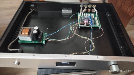
Hello, after many years I finally get the VxD preamp controller (pcb V1.8z) properly installed on a chassis, now I am learning arduino, I download software 1.8.11 Hourly Build, and opened on it the firmware VxD_OLED_4X2s.ino , since my display is oled SSD1309. Now I am stuck could'nt find on computer serial port to upload correct minimum LDR resistances, just first try, soon or later I will.
My main concern is after calibration I get a warning ERROR 1, even after adjusting the bias. Not only, when plug the micro USB to computer, display warns an ERROR 20.
My main concern is after calibration I get a warning ERROR 1, even after adjusting the bias. Not only, when plug the micro USB to computer, display warns an ERROR 20.
Attachments
I've seen Neb's google drive, inside readme file, youtube link instructions, then install correct arduino 1.6.9, fixed libraries, etc. now I have drivers and succeed uploading the firmware, as now is nicer display, it fades light down!
But still same warning: ''ERROR 20 LDR/relay power failure''.
Now I performed a calibration cicle and after 5 min, and 47%, it stuck and warns ''ERROR 1 left series could not be calibrated''
But still same warning: ''ERROR 20 LDR/relay power failure''.
Now I performed a calibration cicle and after 5 min, and 47%, it stuck and warns ''ERROR 1 left series could not be calibrated''
Check relay and soldering, or ldr too lowI've seen Neb's google drive, inside readme file, youtube link instructions, then install correct arduino 1.6.9, fixed libraries, etc. now I have drivers and succeed uploading the firmware, as now is nicer display, it fades light down!
But still same warning: ''ERROR 20 LDR/relay power failure''.
Now I performed a calibration cicle and after 5 min, and 47%, it stuck and warns ''ERROR 1 left series could not be calibrated''
Thanks advice, too late night here europe, tomorrow dissasemble the pcb and check it out if three relays are powered and operate on startup.
By now I measured LDR minimum values, I get: 154, 107, 113 and 123 ohm. I try upload that but my tests on the RCA shokets had same unadjusted values, as if I had not done properly. As seen in pic. attch. I write on all four 'test value' ( PCB 1,2,3,4)
I expected to see more balanced readings after upload.
Attachments

Last edited:
Relay test Ok. and soldering seems OK. many calibrations cicles get Error 1, randomly also get Error 2, and one succeed to complete 100%, but after new biasing... again Error. By now it seems another calibration complete, don't wants to measure again anything, I leave it as it is, will try upload some adjustements into some days, before I need to recover from today amusement.
@JOIMONF, mine is a pain in the a** to calibrate too.
It seems really temperature dependant and if I need to recalibrate it I must plan some hour to avoid error 1.
When calibration is done it works well though
It seems really temperature dependant and if I need to recalibrate it I must plan some hour to avoid error 1.
When calibration is done it works well though
To accommodate new Atmega328PB variant included in LDR Pre MkII, I had to rewrite calibration routine to make it 16-bit instead of 8-bit with range switching. Somewhere along the (long) way, this calibration failure problem has disappeared. I have no idea why🙂 I get errors in LDR Pre MkII only when BIAS is really off.
Well is a relief at least not only me, by no reason is misbehavior.
I thing, that must be stated in advanced on the thread, despite de warnings Error, and altrough still not completing the calibration routine, my VxD controller is in use, I am happy to say, it outperforms -more dynamic and everything- than my previous LDR (so called Lighter Note). So no complains after all.
By now I concealed the warning error 20, I increased line 115 from "#define LDR_FULL_MAX 200" to "#define LDR_FULL_MAX 5000000".
And then I bought a replacement for a somewhat high LDR at 159 ohm minimum resistance. I will post if that fixes.
Could this values I get by now, be considered a properly calibrated volume control?
Pos. RSH LSH RSE LSE
0 180 142 ---- ----
1 181 142 ---- ----
2 116 119 100k 72k
3 167 119 56k 41k8
....
12 178 166 8k9 8k8
13 216 202 8k9 8k8
14 270 245 8k9 8k8
15 330 292 8k7 8k7
16 383 352 8k7 8k7
17 449 412 8k6 8k7
18 522 469 8k5 8k6
19 571 534 8k4 8k6
20 632 589 8k4 8k6
21 702 639 8k4 8k6
22 767 700 8k4 8k6
23 848 772 8k4 8k6
24 911 827 8k4 8k6
25 988 893 8k0 8k2
...
30 1k5 1k4 7k5 7k7
...
35 2k4 2k2 6k8 6k8
...
40 3k7 3k2 5k5 5k6
...
45 5k9 5k1 3k4 3k5
46 6k4 5k6 2k9 2k9
47 7k1 6k2 2k3 2k3
48 8k0 8k7 1k7 2k1
49 18k 20k 1k6 2k1
50 ---- ---- 106 128
Last edited:
- Home
- Source & Line
- Analog Line Level
- Arduino based LDR volume and source selection controller