Hello again
As a result of a few days of effort, it gives error 20 in the first opening. When I look at the error code, I get 12V when I measure R + and A +. There is no problem with the supply. When I turn it on, it opens when I hold down the encoder.
When I made the adjust bias measurements, I was able to set LSE, LSH, RSE to 700K, but although I set RT4, I cannot get any value from RSH.
LSE 71.4, LSH 80.2, RSE 61.5, RSH do not show any value in Measure LDR's measurements.
do i need to change something in the software below for this
// test board
#if PCB == 1
#define LDR_VOLTAGE 5.01 // ** precisely measured value of the + 5V supply (with decimal point. Default: 5.0)
#define LDR_LSE_MIN 54.5 // ** measured value of left series LDR R at maximum current
#define LDR_LSH_MIN 148.4 // ** measured value of left shunt LDR R at maximum current
#define LDR_RSE_MIN 53.7 // ** measured value of right series LDR R at maximum current
#define LDR_RSH_MIN 139.3 // ** measured value of right shunt LDR R at maximum current
#endif
// wooden box
#if PCB == 2
#define LDR_VOLTAGE 5.00 // ** precisely measured value of the + 5V supply (with decimal point. Default: 5.0)
#define LDR_LSE_MIN 57 // ** measured value of left series LDR R at maximum current
#define LDR_LSH_MIN 63 // ** measured value of left shunt LDR R at maximum current
#define LDR_RSE_MIN 71 // ** measured value of right series LDR R at maximum current
#define LDR_RSH_MIN 59 // ** measured value of right shunt LDR R at maximum current
#endif
// gainclone
#if PCB == 3
#define LDR_VOLTAGE 4.93 // ** precisely measured value of the + 5V supply (with decimal point. Default: 5.0)
#define LDR_LSE_MIN 83 // ** measured value of left series LDR R at maximum current
#define LDR_LSH_MIN 114 // ** measured value of left shunt LDR R at maximum current
#define LDR_RSE_MIN 83 // ** measured value of right series LDR R at maximum current
#define LDR_RSH_MIN 130 // ** measured value of right shunt LDR R at maximum current
#endif
I also get an ERROR 10 error when I try to calibrate.
I think you have a problem with RSH. You need to find out why you cannot set RT4 for 700K. Check for solder bridges etc. Check the VN2222 driving RSH. Check orientation of RSH is correct? Maybe try replacing RSH?
Once that is resolved you need to complete this section with real measured values as detailed in the manual :
/******* LDR measured values *******/
#define LDR_R1 10010 //** precisely measured value of R1 resistor (default: 10000 ohm)
#define LDR_R18 10010 //** precisely measured value of R18 resistor (default: 10000 ohm)
// if any measured value is > 200 ohm, replace the LDR. Normal values are around 100 ohm.
// test board
#if PCB == 1
#define LDR_VOLTAGE 5.01 //** precisely measured value of the +5V supply (with decimal point. Default: 5.0)
#define LDR_LSE_MIN 54.5 //** measured value of left series LDR R at maximum current
#define LDR_LSH_MIN 148.4 //** measured value of left shunt LDR R at maximum current
#define LDR_RSE_MIN 53.7 //** measured value of right series LDR R at maximum current
#define LDR_RSH_MIN 139.3 //** measured value of right shunt LDR R at maximum current
#endif
Last edited:
Also though some in this thread have reported VN2222 works the critical VGS(th) spec is much broader (0.6 to 2.5V) than the original 5LN01SP (0.4 to 1.3V). Vincent stated than low VGS(th)was important. So its also possible you are using one which is out of spec.
As mentioned in this thread the ZVNL110A is much better in this respect (VGS(th) 0.75 to 1.5V). The pinout is still different though.
As mentioned in this thread the ZVNL110A is much better in this respect (VGS(th) 0.75 to 1.5V). The pinout is still different though.
hello wineds
how are you
Thank you for your previous help. It took a little longer, but I had to wait for the track. the problem was with RSH.
I can calibrate now when I change the part and fix the software.
My only problem is changing the software according to the current controller.
My remote does not work even though I changed the sections below.
Up key: 104 230 155 127
Down key: 034 060 002 167
Left key: 031 110 001 201
Right key: 046 140 042 137
Center key: 170 123 033 103
Menu key: 029 021 244 215
Play key: 222 201 025 165
(update) The value of the third byte varies from remote to remote. It turned out that the 8th bit
is not part of the command, so if we only read the 7 most significant bits, the value is the same
for all the remotes, including the white platic remote.
The value for the third byte when we discard the least significant bit is:
Up key: 104 230 155 127
Down key: 034 060 002 167
Left key: 031 110 001 201
Right key: 246 140 042 137
Center key: 170 123 033 103
Menu key: 029 021 244 215
Play key: 222 201 025 165
I got the hex codes of my remote with arduino
up - 68 E6 9B 7F
down - 22 3C 02 A7
left - 1F 6E 01 C9
rıght - 2E 8C 2A 89
center - AA 7B 21 67
menu - 1D 15 F4 D7
play - DE C9 19 A5
When you got the hex codes of your remote did you also get the protocol it is using?
The Apple remote uses NEC protocol and my quick look at wineds's code shows he decodes NEC protocol and only NEC protocol.
The Apple remote uses NEC protocol and my quick look at wineds's code shows he decodes NEC protocol and only NEC protocol.
The code was written by Vincent. Myself and others have added to it and improved it. It only supports apple remotes. And you really need a genuine one.
Hello there
After a long time I tested the complete circuit. but I have a problem.
It has 3 inputs and 1 output but I only get one channel output.
There is no single channel output from the arduino system.
also moaning at inter-canal change
After a long time I tested the complete circuit. but I have a problem.
It has 3 inputs and 1 output but I only get one channel output.
There is no single channel output from the arduino system.
also moaning at inter-canal change
Hi Vincent,
Your design has important advantages over classic lightspeed attenuator. But, you use some relays on the signal path. Isn't it a controversial approach against no contact point targeted by lightspeed. Have you ever compared yours to original lightspeed side by side for audio quality? What is your impression?
Your design has important advantages over classic lightspeed attenuator. But, you use some relays on the signal path. Isn't it a controversial approach against no contact point targeted by lightspeed. Have you ever compared yours to original lightspeed side by side for audio quality? What is your impression?
Last edited:
Hi Vincent,
Your design has important advantages over classic lightspeed attenuator. But, you use some relays on the signal path. Isn't it a controversial approach against no contact point targeted by lightspeed. Have you ever compared yours to original lightspeed side by side for audio quality? What is your impression?
Sorry, I haven't seen your question until today.
Quote from the description of the project on page 1: "I/O switching is done with best quality latching relays with Silver-Palladium contacts, to avoid any degradation of the musical signal"
So, the contact quality should be better than that of most interconnect cables. The relays are not powered during normal use (they are latching relays), so there is no EM field close to the signal.
Would this work to switch between 2 balanced xlr amplifiers?
Yes, but you have to customize the I/O relays for the required 3PDT switching.
Dear all,
I have an LDR Pre MkI made from zdr complete with lcd that I had taken for a project but it was never done until about a month ago when I took the board to make a preamp with the Nelson Pass B1 with the korg nutube. Unfortunately I can't get them to work together, in the sense that if I make them work alone, they are perfect, if I connect the preamp to the right of the pcb the sound is completely distorted, the volume stops working and has a strange behavior when the volume changes, distortion varies and when it is at its maximum, the signal disappears. I tried to change impedance, resistance range, volume amplitude (50 to 30) but always without success. I tried to put the pre in series with the output and it works perfectly, at this point I am wondering if I have to configure something at the software level, so here I am asking you how you connected and configured your LDR Pre MK1 with an active preamp.
Thanks to all and happy Saturday!
It works fine when not connected with the B1? Then the issue is not with LDR. I have mine connected with rmi-fc100, no problems at all.
Does your b1 work with a simple pot? What are the signal levels you are feeding?
Does your b1 work with a simple pot? What are the signal levels you are feeding?
I made a few attempts, I assembled the B1 with a potentiometer and it works without a problem and the card with the LDR works perfectly by itself, I feed them with a normal dac, so I think the maximum output amplitude can be around 2V.
One of these evenings I should put together a fet based preamplifier (Preambolo taken from TNT Audio website) which I will try to connect with the LDR board to see if the problem occurs due to an incompatibility with the board with the korg chip. If anyone can think of anything about any configurations, please let me know.
Good day everyone
I have my Korg Nutube B1 paired with the zdr's LDR volume control and it works perfectly fine. No issues at all.
thanks
thanks
Dear man Iran,
thank you for confirming that there are no incompatibilities with the korg nutube b1, this encourages me a lot to continue on the project. I was wondering if it was possible to see some photos of your creation.
Thank you very much and good evening to all
thank you for confirming that there are no incompatibilities with the korg nutube b1, this encourages me a lot to continue on the project. I was wondering if it was possible to see some photos of your creation.
Thank you very much and good evening to all
dear manniraj,
the damn proofreader has cheated me again ... forgive me if I misspelled your name.
the damn proofreader has cheated me again ... forgive me if I misspelled your name.
i don't know where to bang my head, i'm trying with a pre to JFET and the problem is the same, alone the two boards work perfectly, exactly like with Korg Nutube B1, when i connect in series the LDR board and the pre, it works well, if instead I connect the pre to the relative sockets on the right of the LDR card I have this type of result:
Volume at 0 out of 50: no signal
Volume from 1 to 11/12 out of 50: maximum distortion at 1, descending until it almost disappears at 12, but very little variation in volume.
Volume from 13 to above 40: distortion from minimal to zero, the sound changes character becoming full, with almost no change in volume amplitude.
Volume above 40: the sound becomes thinner and thinner, losing all the bass, the amplitude of the volume decreases slightly.
Volume at 50: no signal
Exactly the same problem I had with the Korg.
The firmware I used is the one I found in the google drive, I set the resistance value of the LDR to 22K and I calibrated the trimmers and detected the resistance values of the LDRs as instructed by reporting them in the relative fields of the firmware.
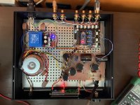
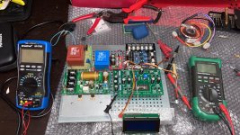
I am attaching a couple of photos of the realization, maybe I made a super mistake that I can't see.
Also, maybe even this is needed, after two or three hours of operation, I noticed that in the power supply of the LDR board the transformer and heatsinks are quite hot, nothing to worry about, I can touch them with my fingers, but find a transformer that is not cold in a card for low signals had never happened to me.
Thank you for the help you are giving me.
Volume at 0 out of 50: no signal
Volume from 1 to 11/12 out of 50: maximum distortion at 1, descending until it almost disappears at 12, but very little variation in volume.
Volume from 13 to above 40: distortion from minimal to zero, the sound changes character becoming full, with almost no change in volume amplitude.
Volume above 40: the sound becomes thinner and thinner, losing all the bass, the amplitude of the volume decreases slightly.
Volume at 50: no signal
Exactly the same problem I had with the Korg.
The firmware I used is the one I found in the google drive, I set the resistance value of the LDR to 22K and I calibrated the trimmers and detected the resistance values of the LDRs as instructed by reporting them in the relative fields of the firmware.
I am attaching a couple of photos of the realization, maybe I made a super mistake that I can't see.
Also, maybe even this is needed, after two or three hours of operation, I noticed that in the power supply of the LDR board the transformer and heatsinks are quite hot, nothing to worry about, I can touch them with my fingers, but find a transformer that is not cold in a card for low signals had never happened to me.
Thank you for the help you are giving me.
Attachments
What is the exact version of firmware you are using? Why did you change it in the first place? You received arduino with firmware already in.
Upload a close up photo of the ldr board.
Upload a close up photo of the ldr board.
Dear man Iran,
thank you for confirming that there are no incompatibilities with the korg nutube b1, this encourages me a lot to continue on the project. I was wondering if it was possible to see some photos of your creation.
Thank you very much and good evening to all
Here you go for couple of pics


- Home
- Source & Line
- Analog Line Level
- Arduino based LDR volume and source selection controller