Hi zdr.
My board is 2.2z.
I would like to add an op amp buffer just before the two output relays .
As there is no schematics available, can you tell me if there is a best trace to cut?
I don't really understand how mute and calibration relays are used when calibrating, perhaps it's a bad idea and will disturb calibration procedure?
Thanks in advance.
Best regards
RMI-FC100 is class A until 8W so there is some heat dissipated, but it can be biased for less dissipation. Better to ask for details in the FC100 thread.
I thought it was only class A until 2w? viz :
Class A power: 2W rms into 8ohm with Iq=0.6A (maximum Iq for optimal B class bias)
zdr,
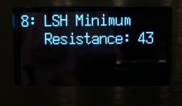
Is there any easy way to test for ldr failure since I can't get past error 20 to measure them. I am getting approximately 5V across the three relays, which should be enough for operation. I am using the NSL-32R3 in this build; which I believe you have said in past posts were slow on calibration but should work.
Regards,
Roy
Roy, did you check that the LDRs are orientated correctly? On my last build I had error 20 due to an incorrectly orientated LDR (white dot had worn off).
Yes, all my dots are in a row. I have one that has the top engravings reversed from the others but I have seen that on other builds that operated correctly.
Measure the resistance of each ldr, I think they should still be in ON state during error 20.
I thought it was only class A until 2w? viz :
Class A power: 2W rms into 8ohm with Iq=0.6A (maximum Iq for optimal B class bias)
Indeed, i confused watts with ohms😉
Hello
@zdr , not any clue for a trace where I can add buffer before the two output relays?
I really would like to add a buffer.
If I refer to Vincent77 schematics it seems calibration relays disconnects output when calibrating, am I wrong?
Best regards
@zdr , not any clue for a trace where I can add buffer before the two output relays?
I really would like to add a buffer.
If I refer to Vincent77 schematics it seems calibration relays disconnects output when calibrating, am I wrong?
Best regards
R6 relay
Hi,
I have a tube preamp that needs to preheat the tubes before applying full B+ voltage, I want to use the "+ R6" header on the board to connect a SPST low current 12v relay.
Is this model of relay (G2RL-1A-E-ASI DC12) can make the job ?
How I connect the coil ? +12V at one side and R6 at the other side ?
Thanks for ansewering and best regards
sounds like it should work!
It’s still under test. It requires a hard modified version of Arduino Nano with Atmega328PB to utilise all available 16bit timers. There is no more high/low range switching causing volume bumps, so the dac hardware is also modified. Power supply is fully on 5v, no 12v any more.
- Home
- Source & Line
- Analog Line Level
- Arduino based LDR volume and source selection controller


