ah...typo...sorry is bad if i missreading..How C12 can be 0.9V ? That should be rail voltage +20V.
What PSU are you using? What current amp draws without output devices?
Is your positive rail voltage going to 0.9V on idle amp that doesn't even draw significant current?
I'm assuming LOW current, so the positive rail shouldn't sag, and Voltage on C12 should show +20V (or whatever your voltage supplies exactly are, little bit over 20V I guess).
C12 is wrong! it is C10
if i desolder C6 should i measure?

So now without C6 and output devices, the only connection between output and any voltage source, can happen only via T5...
One more thing to try - remove D1, and check output voltage..
Check if C6 is not damaged (measure capacity, and check for shortage).
One more thing to try - remove D1, and check output voltage..
if i desolder C6 should i measure?
Check if C6 is not damaged (measure capacity, and check for shortage).
if is switched on DC offset is fine...but it is risingwithout C6
DC offset is now -22,4V
and at the base of T5 i measures -22.2V without C6
T1 needs biasing - usually it's R from the base of T1 to the GND.
Here R5 is connected to ground via R8, so some part of the feedback AC signal will be send to T1 (besides T5).
I've seen this before on some amps, but not sure what problem exactly it's trying to solve....
Value of R5 usually is similar (or the same) to R10 (feedback resistor).
Diode D1 is supposed to clamp IPS differential output voltage to prevent saturation of the current mirror (T2/T4) when the amp clips.
Usually there is 2 diodes in parallel, in opposite directions.
Last edited:
omg 🙄
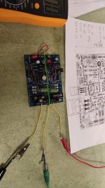
i de solder D1 and T5 both components are checked and fine
C6 is out
all measurements from GND
now i get - 22.4 DC offset on the speakers and on the base of T5 too???!!!
T5 GND to Base -22,4V
T5 GND to Collector-22,9V
T4 GND Collector -22.9V
T2 is off
R3+R6 no Voltage
T1 GND Emitter -13,9V
R5 zero Volt
What??
Last edited:
no electrically shorts...it is a not so complicated amp...i guess....but i am a noob.
no...nobody did build this amp except the developer APEX
i am actually *#&%$§ off this amp....but i will learn i lot...i am sure 😉
no...nobody did build this amp except the developer APEX
i am actually *#&%$§ off this amp....but i will learn i lot...i am sure 😉
Hi
I don’t have sufficient knowledge to help you troubleshoot but I admire your patience and perseverance to you both 👍
Hope you find the issue.
Eric
oh thanks Eric !
yes ...it is partly a nightmare.. but i have to do like Water:
slow water hollows out the stone
i checked with my beeper (ohm meter) a new pcb for shorts but i found nothing...so the quality should be fine
- Home
- Amplifiers
- Solid State
- Apex AA14 Amp Class A 24V Supply