
no problem 😉
you are the only one to try to help me. i invest my time to my second APEX FX8 and then .....call it a day.😎
🙂
you are the only one to try to help me. i invest my time to my second APEX FX8 and then .....call it a day.😎
🙂
next step.
recheck all resistor values.
check diodes...not all can be measured if they are soldered in
maybe the resolder R15 and R16(ripple eater) and split the amp into ips and ops. and try to supply the ips and check...will see
recheck all resistor values.
check diodes...not all can be measured if they are soldered in
maybe the resolder R15 and R16(ripple eater) and split the amp into ips and ops. and try to supply the ips and check...will see
What I would do in this case - perhaps develop lt spice model, verify if it works as supposed to (e.g. idle current control), and then compare voltages/currents
in certain points of the schematic between the model, and the prototype, to see if it matches the model.
Wrong voltages will tell you WHERE is the problem, or possibly which transistor is burnt (if that's the case).
As for that extra GND wire - you are sure that 'X1-2' point (in the schematic) is connected by a wire to PGND point (in the schematic)?
I did thisHi Minek
i did the test. i take an extra cable and put it at the minus terminal of the input terminal but the amp doesn't work again.
same behavior as wrote above-
could it be that the mica caps are to high?--> oscillation?
C10/ c11 22pF for the VAS transistors
or the feedback cap C8 is too high 33pF
kr
chris
As you wrote in Post #9
Hi Minek
I check all resistor values - okay
diodes ok
all small BJT ok.
bigger BJT okay...
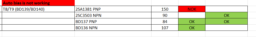
then i realized that the onsemi 1381 NPN is with hfe about 150 too much for the "auto biasing function" because if i change to the BD137 and BD136 which i had in the box- both amps are working and the ocp is not get on.
bias is starting with 1,44A @ 24 Volt and goes on one amp quicker then the other down to 1,250A
okay fine. but...
i had on the speakers measured the DC offset and i got at start up of the PSU 15Volt !! and then it gets more or less slowly down to 5V.
****.......this is bad!
so enough for today...
chris
I check all resistor values - okay
diodes ok
all small BJT ok.
bigger BJT okay...
then i realized that the onsemi 1381 NPN is with hfe about 150 too much for the "auto biasing function" because if i change to the BD137 and BD136 which i had in the box- both amps are working and the ocp is not get on.
bias is starting with 1,44A @ 24 Volt and goes on one amp quicker then the other down to 1,250A
okay fine. but...
i had on the speakers measured the DC offset and i got at start up of the PSU 15Volt !! and then it gets more or less slowly down to 5V.
****.......this is bad!
so enough for today...
chris
Attachments
You mean T9 ? This is VAS transistor, not part of 'biasing' circuit.
1381 should be perfect for VAS...
T10,T11,T12, T13 are doing biasing..
Measure voltages between bases of T14/T15 to see bias voltage.
If amplifier behaves differently after you replaced T9 with 1381, perhaps it is oscillating...
Possible, spice sim would confirm this...
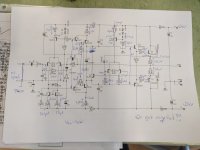
By any chance - you didn't forget to solder the wire connector in the center of the PCB?
Between R17 and D4. Can't see it on your photo...
1381 should be perfect for VAS...
T10,T11,T12, T13 are doing biasing..
Measure voltages between bases of T14/T15 to see bias voltage.
If amplifier behaves differently after you replaced T9 with 1381, perhaps it is oscillating...
Possible, spice sim would confirm this...
By any chance - you didn't forget to solder the wire connector in the center of the PCB?
Between R17 and D4. Can't see it on your photo...
Last edited:
Hi Minek
thanks for your time and help.
i was happy that the OCP is not working 😉...first step done.
okay yes i see that the BJT T10-T13 are doing biasing. i am not an expert ....but you know..😛
sorry ...but LT spice ...i can not...i dont know
no...i made a connection from PGND to input X1- 2(sign GND)
no...the connection (wire) is done between D4 and R17....all other 2 wires too. (see pic)
yes i will do on the weekend some checks
kr
chris
Attachments

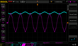
S**t...i build an oscillator 😕🙄
50HZ ??
Q1 getting very hot very fast:
Measurements:
bases T8 / T9 33,88V
bases T14 /T15 3V and get down to 2,81V
bases T6 /T7 33,88V
GND to base of T1 0,3V
GND to base of T5 9,4V
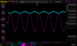
pic: ch2 DC_blue...ch3 is the probe AC to some points
pic named with base
is with the probe pink at the Base of Q1, blue is the DC offset with a differential probe on the speakers output (from 15V to 5)
all other measurements show the same high swinging value !!
i have no idea what i do next because the Q1 is getting very fast super hot 100°C ! is 5 seconds!!
kr
chris
50HZ ??
Q1 getting very hot very fast:
Measurements:
bases T8 / T9 33,88V
bases T14 /T15 3V and get down to 2,81V
bases T6 /T7 33,88V
GND to base of T1 0,3V
GND to base of T5 9,4V
pic: ch2 DC_blue...ch3 is the probe AC to some points
pic named with base
is with the probe pink at the Base of Q1, blue is the DC offset with a differential probe on the speakers output (from 15V to 5)
all other measurements show the same high swinging value !!
i have no idea what i do next because the Q1 is getting very fast super hot 100°C ! is 5 seconds!!
kr
chris
Attachments
my next try will be that i measure all resistor values,
btw. i use rail 20V and my PSU show that the auto bias is"working" because of the input current is 1,4xxA and then gets down to 1,25xA.
this current is stable
btw. i use rail 20V and my PSU show that the auto bias is"working" because of the input current is 1,4xxA and then gets down to 1,25xA.
this current is stable
I would check Vdrop on R18, if T12 is in wrong -no current will flow and there is no current for T10, am I right?
He wrote:
T10,T11,T12, T13 are doing biasing..
as i can see at the psu rails that the bias is working as set by the designer...starts with about 1,4A and goes down to 1,255A. so i gues thta the auto biasing is working. i try 20 v rail or 24V..it doesn´t matter...it works.
tomorrow i will do the values as i wrote above
measurements: from post 34
bases T8 / T9 33,88V
bases T14 /T15 3V and get down to 2,81V
bases T6 /T7 33,88V
GND to base of T1 0,3V
GND to base of T5 9,4V
new.
i switch on an measured as fast as i can and then switch off a wait a bit for the next measurements because of Q1 gets f** hot! so the current is in the startup phase about 1,4A.
OPS:
Q2 Vbe 0,61V , R22 base 45mV, R24 0,22R 316mV
Q1 Vbe 0,51V , R23 base 31mV, R25 0,22R 319mV
R21 1,76V
Auto bias area:
R20 22,6V, R18 0,59V, VCE T12 0,59V
R19 0,66V, R17 0,95V
VAS:
R13 1,2V, R11 20,38V, R12 20,1V, R14 1,52V
IPS:
R4 0,6V, R5 31,6mV, R6 301mV, R3 303mV
Hi MinekIf it is really oscillating,
you could try these things:
a) increase C10/C11 (e.g. try 33p, 47p, 68p, 100p)
b) increase C8 (47p, 68p, 82p, 100p)
The lower values - the better.
my estimation is that it makes actually no sense to change this caps because the ringing is gone but i have still to high DC OFFSET.
Does it makes sense to "cut " the Amp in to half's with de solder the R15 R16 (ripple eater) to power up the IPS separate?
kr
chris
I'm looking at the voltages you posted, and all input/vas voltages look normal, with exception of base T5 - but this is a consequence of the DC offset on the output.
Next step would be to analyze how the biasing circuit works, and try to make sense of these voltages.
I guess that would be the best time to use LT Spice..
My suspect responsible for the DC offset is biasing circuit (assuming that drivers are working fine, not burnt/shorted, etc..).
How did you check if drivers and output devices are fine? Transistor tester?
- Home
- Amplifiers
- Solid State
- Apex AA14 Amp Class A 24V Supply