Emails
Hi folks
I have been receiving quite a few emails lately about some of my amp designs. This is not a problem at all and I try to answer every email. Sometimes though I cannot do so for a few days and I wonder if some of the enquiries I receive could be posted here.
These would probably get a faster response from other contributers, many who probably have built more than I have. They could also offer their ideas and their real life experiences.
I'm still happy to answer direct emails, but it might just take a bit longer. Sometimes if I feel the enquiry and answer would benefit others I might post the email here anyway.
Cheers
Quasi
Hi
I have a plan to build this Actrk600 amp with IRF460 6 pairs for my PA application. Could anyone tell me how much the PCB board measure?
Tks
I have a plan to build this Actrk600 amp with IRF460 6 pairs for my PA application. Could anyone tell me how much the PCB board measure?
Tks
Bushulo said:Hi
I have a plan to build this Actrk600 amp with IRF460 6 pairs for my PA application. Could anyone tell me how much the PCB board measure?
Tks
Hi Bushulo,
The Actrk600 PCB measures 262.9mm x 69.9mm
Cheers
Q
" Post #427
Hi Kanwar
Interesting....
The opamp shown could be replaced with discrete differential stage I imagine?"
William Chatter has a couple of designs based on this idea in old Audio Amateur and Glass Audio magazines.
His concept diagram shows opamps in a suspended supply arrangement, his circuit uses a discrete opamp. The version in Glass Audio uses tubes (of course).
One easy way to do this is to drive ground with the outputs (QSC style). Two nice quad opamps can drive four complementary pair. Use a simple follower on the opamp if you want lots of current at high frequency. No matching and no temp compensation.
Hi There Quasi,
The high power version of the ACTRK600 saw some daylight on the weekend... for a friends 30th birthday in terms of performance - driving the L+R speakers for ~5h solid the last 2 hours at quite high volume the amp did not even click on to use the fans.
see pic attached of the amp on the bottom left in a red TDI volksy transporter LWB.
-Dan
Attachments
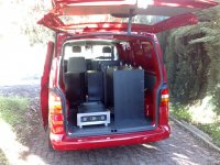

Good to get the update on the amp Dan. Are the fans ok?...just kidding. Looks like you turned the sound pressure up.
Cheers
Q
Cheers
Q
Hi Folks,
I will be away for about 7 days attending a conference in Phuket -Thailand. Please don't feel sorry for me, I had it coming. Of course if any fellow DIY'ers happen to be in Phuket over the next week send me an email and I'll give you some details. There will not be any posts from me during this time.
Try not to burn yourselves with your soldering irons and I'll try not to burn myself in the sun.
Cheers
Q
djk said:" Post #427
Hi Kanwar
Interesting....
One easy way to do this is to drive ground with the outputs (QSC style). Two nice quad opamps can drive four complementary pair. Use a simple follower on the opamp if you want lots of current at high frequency. No matching and no temp compensation.
Hi DJK,
you mean Grounded Source Amplifier, its very easy to do in this configuration, but availability of P-channel mosfet is the main concern, thats why i struck to N-chanels only. but yes lower power amplifier with rails less than 100VDC would be worth.
😉
danieljw said:Here was the setup
hi danieljw,
what are the tools or hardware for set up monitoring from the laptop? i just want to know this please. any harware or card and the software to connect in your laptop? thankz.
Hi there ROHMS,
I was just using windows media player for the player, and the software in the picture was the trial version of SMAART 6 from EAW (eastern acoustic workshop)
get it here:
http://www.eaw.com/products/software/EAWSmaart/download.html
There was not trickery in terms of delays etc etc it was a stereo setup with mono bass
-Dan
BUZ901DP Lateral mosfet needed
HI Hienrich
Unfortunately I'm unable to contact direct with you .The reason why I'm writing I would be interested on 4PC BUZ901DP lateral mosfet if you still have them .
Or please let me know were I can purchase in a good price .
I have 4PC BUZ906DP and I'm unable to use them because I do not find the complementary pairs .
Please help me if you can .
Thanks
Regards
hienrich said:hi there guys,
I have some couple of BUZ901DP in my drawer, and Im
planning to use this on NMOS200 project.
my question: what issues will I encounter when using
these devices?
if ever there must be, and since I have not much
experience
on Lateral Mosfets, what would be your advice ?
cheers
ps: Quasi 😉 you've got a good selection in your site
congrats

Hi
I've constructed a Nmos200-amp on a PCB of my own design (I can take pictures on request).
It works perfect. Almost....
PSU is 200W IE-core, bridge and 6*2200uf (single channel). Unloaded rails are approx +/- 58V. Drops to ~ 52 under full blast. Sound is clear and not distorted (or not distorted enough to trigger my ears 🙂
The amp is completely silent with no connections to the input
Two problems:
1) A 1KHz sine is perfectly clean and clips in a very controlled matter. A 30Hz doesn't clip very nice. (Pics can/will follow). Has anyone else seen this?
2) I had the amp connected to my computer. That generates some noise. I suspect the noise was due to switcmode-noise and differences in GND-potentials. At some point the gnd-clip (of the input from the computer) slipped. That lead to amp to a 80Vpp Mhz clipped signal at the output..... Not good.
The amp didn't self-destroy, but I suspect that it could under those conditions? Has anyone else experienced that?
Thanks for the help.
Regards TroelsM
Does anyone know if the BUZ901/906 (double die) mosfets can be used with the Nmos?
I have a number of them that are not being used. Also will I have to modify the amp to get the BUZs to work or just a straight replacement?
Thanks
Lawrence
I have a number of them that are not being used. Also will I have to modify the amp to get the BUZs to work or just a straight replacement?
Thanks
Lawrence
quasi said:Hi Ilimzn,
As you can see I've been thinking about the theraml tracking for quite some time. I wonder if you could provide a rough sketch so that I could be clear about what you mean by "ring ccs". I read it as a double ended ccs so a drawing would remove any confusion.
Everything else you say of course makes sense.
Cheers and thanks for your input.
Q
Sorry for replying so late to this thread - it seems the 'thread watch' feature does not work well for me.
A ring-of-two CCS is normally made with two BJTs. Here is a variant that uses a PMOS to sense the current. The top of the circuit is the +V rail for the driver. The BJT collector is the CCS output. The current is of course roughtly the MOS treshold voltage divided by the BJT emitter resistor. Two possible ways of setting the current can be implemented - either varying the BJT emitter resistor or the base biasing resistor. If the +V rail of the driver is not regulated, the base bias resistor can be split into two and a bootstrap cap conencted from their midpoint to the +V rail of the driver. The 1n cap is for compensation, and it can actually be made quite large.
Attachments
Re: Nice Work Dan
hi quasi
which biasing technique to consider the above one
or the one on your website if i follow the one on your website the things are going wrong i cannot set the bias. the voltages does not go beyond 4.3 volts across 100 ohm positve rail resister.i checked everything and seems to be ok. i mount t4 this way please say something quasi
http://i35.tinypic.com/k0lfmo.jpg
quasi said:
Very nice work Dan,
In your case the first and second stages need about +105 volts and this should be referenced to Gnd. The easiest way to get this is by winding extra turns on your transformer secondary and half wave rectifying and smoothing as shown in the power supply schematic on my web site. Alternatively, to just prove the amp is working you can connect this stage to the main positive rail and sort it out later.
When you first set up for biasing, replace the two fuses with 100 ohm resistors. Then turn the biasing control so that you have maximum resistance between the positive rail and the emitter of T5.
Place a voltmeter across the 100 ohm resistor on the positive rail, switch on and adjust the trimpot until you see a voltage (about 1 volt) across it. Wait and watch the reading for a few minutes, it should continue to rise slowly. Once it seems to have settled adjust again to 3 or 4 volts. This will have set about 40 milliamps through the output stage. Pause here and connect a CRO to make sure the amp is working with a small signal. Do not consider the voltage across the 100 ohm resistor on the negative rail as bias current indication.
All being well switch off and remove the 100 watt 5 watt resistors and place a 1 amp fuse (not a 10 amp) in the negative rail fuse holder and a 10 ohm 5 watt resistor in the positive rail fuse holder. Back off the adjusting trimpot a bit before you turn on again.
Switch on and adjust the trimpot slowly, pausing and waiting to allow the amp to settle until you get about 1.8 volts across the 10 ohm resistor. This has set the output stage bias current to 180mA.
When this is done center the output using VR1, and do a final check on the bias. When you're happy, remove the 1 amp fuse and the 10 ohm resistor and replace both with 10 amp fuses.
This is a bit more tedious than most amps, but it's a characteristic of the simple design.
If you want, we can make a time to do it together.
Cheers
Q
hi quasi
which biasing technique to consider the above one
or the one on your website if i follow the one on your website the things are going wrong i cannot set the bias. the voltages does not go beyond 4.3 volts across 100 ohm positve rail resister.i checked everything and seems to be ok. i mount t4 this way please say something quasi
http://i35.tinypic.com/k0lfmo.jpg
Quasi
if 4 volts per output pair it is almost impossible to get 24 volts across positive rail resistor.
thanks in advance
if 4 volts per output pair it is almost impossible to get 24 volts across positive rail resistor.
thanks in advance
BUZ laterals
HI Andrew
I need the laterals for something another design .
I wrote to Magna tec but they never answer back .Unfortunately these laterals no longer available in N America .
Regards
HI Andrew
I need the laterals for something another design .
I wrote to Magna tec but they never answer back .Unfortunately these laterals no longer available in N America .
Regards
- Status
- Not open for further replies.
- Home
- Amplifiers
- Solid State
- Another quasi-complementary design