Hi all,
- Thanks Quasi, I am pretty pleased wqith the power output from your design... will do four Ohm measurements in a few days.
- Hi Anthony, the line voltage was about 245-246vac so it was high that day 🙂
i ended up with just over 94 Vdc per rail at idle and 90 Vdc under load, supply could be better but its not too bad.
-Dan
Hi,
90Vdc on the loaded supply rail.
89.94Vpk at the load.
10Apk passing to the load.
Is 56mV drop through the output FETs and wiring and PCB traces and source resistors and...
Is that possible?
90Vdc on the loaded supply rail.
89.94Vpk at the load.
10Apk passing to the load.
Is 56mV drop through the output FETs and wiring and PCB traces and source resistors and...
Is that possible?
I think the VAS allows virtually rail to rail swing on this one Andrew, However my qualifying statement is..... It could be a little more than 90Vdc on the loaded rail I can always check again.
-Dan
-Dan
Hi all,
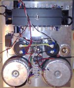
Finally at the stage where i can case up the ACTRK600's
Very happy with the performance so far..........
here is a pic of the first heatsinking arrangement.....
the ac driven fans with bimetal thermal cut in proved to be noisy
electrically and mechanically. The airflow was not optimal.
I would have needed a tube of some sort to direct the airflow front to back or side to side..........
Attachments
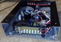
Thermal mods.....
I got busy on the weekend and changed the heatsink to a Conrad 150 x 300 x 35 which i is sandblasted that i had laying around.
It took some effort (drilling approx 1 billion holes )
)
However now I can fit both ACTRK600 modules, DC protection/anti thump, and NTC. temp controller on the heatsink and all are easily accessible for adjustments/setup. not to mention the ariflow is front to back 😀
I got busy on the weekend and changed the heatsink to a Conrad 150 x 300 x 35 which i is sandblasted that i had laying around.
It took some effort (drilling approx 1 billion holes
)However now I can fit both ACTRK600 modules, DC protection/anti thump, and NTC. temp controller on the heatsink and all are easily accessible for adjustments/setup. not to mention the ariflow is front to back 😀
Attachments
Good job !
Btw, positioning the fins vertically could provide better air flow.
When its time to conquer mosfets, i'll pick quasi's actrk600...
Btw, positioning the fins vertically could provide better air flow.
When its time to conquer mosfets, i'll pick quasi's actrk600...
Hi Rolandong,
I agree but - I probably should mention there are fans to go on the front of the heat sink drawing (hopefully) cooler air from the back and exiting it from the front of the case... havent put them in yet!!
I agree but - I probably should mention there are fans to go on the front of the heat sink drawing (hopefully) cooler air from the back and exiting it from the front of the case... havent put them in yet!!
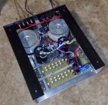
Man that's a tough mean looking case. Where did you get that C section? I like the way you've used it.
Just one suggestion, have you thought about moving the small toroid to the other side. Where it sits now is right next to the input stage.
Nice work Dan, how does it all sound?
Cheers
Just one suggestion, have you thought about moving the small toroid to the other side. Where it sits now is right next to the input stage.
Nice work Dan, how does it all sound?
Cheers
Hi,
I don't know if it's ever possible to use a pair of ACTRK600's hard.
If they do need a lot of heat removed, then it would be better if that heat was pushed straight out the back and not in the direction of the PSU.
The second amp will run hotter than the second unless you have moved the contact surfaces towards the cold side of the heatsink (the side nearest the "blower").
Make sure your blower or sucker is ducted to ensure the cooling air stream actual passes the heatsink. Also ensure that you do not recirculate the heated air back around the fan assisted circuit (just like the recirc inside a Japanese car).
Hi All,
Quasi,
thanks for the compliment, It looks alot better with the 12mm alumnium front panel on 🙂 the c section is structural Al. from "smart aluminium" its quite expensive 🙁 but the case is up for alot of abuse not that it will see it....
I did think i may have to move the small toroid but there is absolutely no audible hum / hiss form this thing i am really happy with the sound 🙂 (good point though)
________________________________________
Andrew, in response:
its possible in a party situation, or driving a subwoofer to drive ACTRK600s hard!!!!!
Q, If they do need a lot of heat removed, then it would be better if that heat was pushed straight out the back and not in the direction of the PSU.
A, why do you choose this way ?
most commercial designs use the opposite. A benefit is you can judge the temp via exiting air, the power supply is not really the main source of heat in this particular amplifier ? ( correct me if i am out of line here) either way after a given period of time the whole thermal system will stabilise at some level above ambient...
Q, The second amp will run hotter than the second unless you have moved the contact surfaces towards the cold side of the heatsink (the side nearest the "blower").
A, I agree with you here however based on testing so far the heatsink temperature rise will not be dramatic. ie less than 30K.
Q, Make sure your blower or sucker is ducted to ensure the cooling air stream actual passes the heatsink. Also ensure that you do not recirculate the heated air back around the fan assisted circuit (just like the recirc inside a Japanese car).
A, LOL I have a Japanese car 🙂 The fans are going to be mounted in the front panel area virtually touching the heatsink i can run them at very low speed via the small thermal control (the blue pcb on the heatsink) and full speed when the amp gets really hot. if its being used for a party 🙂 in which case you wont hear them !!!
Thanks for your comments, I am interested to hear your opinions on the cooling airflow, I think I will make up my mind based on actually testing what works best in terms of front/back back front etc etc
still have not done the 4Ohm test....
-Dan
Hi,
all the components in the PSU will generate a little heat.
The manufacturer of each will specify the maximum temperature, either ambient or component, that each can run upto.
Some components will have a much shorter life if run at near maximum temperature repeatedly.
You want cold air around the PSU, NOT heated air coming from the sinks.
I think I have back and front swapped, I hope you understood which I meant from the context.
don't use yK for delta T. yC or yCdegrees can be used this way. xdegC or xK are absolute temperatures.less than 30K
Bias control and thermal tracking;
Greetings fellow DIY'ers
I have been thinking lately about how to improve the thermal tracking of the bias control. In it's current setup the bias setting is a little fiddly and because of the way the tracking transistor is mounted, may respond too slowly depending on the thermal mass of the heatsink used.
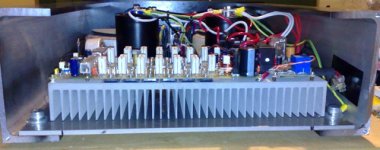
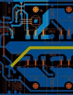
So I have come up with an alternate arrangement for consideration. In this arrangement the tracking transistor (T4) mounts directly on top of the first output FET through a hole drilled in the PCB. The transistor is held down by a small clamp secured by T9's mounting bolt / screw. I have attached a pic to show the arrangement (poorly).
In this way T4 will track the temperature changes of the FET directly and react more quickly. It does not matter if the chosen FET is at a different temperature from the others as we only need to track a relative change.
T4 is now easier to mount as well. Anyway your thoughts please.
Cheers
Quasi
Greetings fellow DIY'ers
I have been thinking lately about how to improve the thermal tracking of the bias control. In it's current setup the bias setting is a little fiddly and because of the way the tracking transistor is mounted, may respond too slowly depending on the thermal mass of the heatsink used.
So I have come up with an alternate arrangement for consideration. In this arrangement the tracking transistor (T4) mounts directly on top of the first output FET through a hole drilled in the PCB. The transistor is held down by a small clamp secured by T9's mounting bolt / screw. I have attached a pic to show the arrangement (poorly).
In this way T4 will track the temperature changes of the FET directly and react more quickly. It does not matter if the chosen FET is at a different temperature from the others as we only need to track a relative change.
T4 is now easier to mount as well. Anyway your thoughts please.
Cheers
Quasi
Attachments
Hi,
it's close enough to ignore cable effects.
DC offset shutdown circuitry must be implemented. Otherwise there is a small risk of measuring the temperature of the cooler side of the amplifier.
But, has anyone tested the arrangement where a SOT23 transistor is glued to the Drain/Collector pin right next to the output transistor package.
This should react very quickly. Primarily due to the short, thick, copper lug connected direct to the transistor substrate, but also due to the very low thermal inertia of the tiny SOT23 package.
Again this route is fairly short to the nearest Drain pin.
Which face of the SOT23 is closest to the substrate, or is it so thin that both faces are equally thermally conductive?
Hi Quasi, AndrewT
This mod will improve the response, but it will cause the
Vbe multiplier to over compensate.
I first used mounting the Vbe device onto of the Output FETs
back in 1994. On My 350 watt design (AV400) that was published in June 94 issue of Silicon Chip Mag.
It worked well to protect the output stage from thermal runaway but it throttled the bias right back to almost nothing.
The partial fix was to use a LED in the emitter leg of the Vbe device, this reduced the gain of the Vbe but did not completely
fix the issue. A further improvement was to remove the LED and replace it with a 82 Ohm resistor.
This stablised it quite well, but it still over compensated a small amount.
Hi Andrew, completely agree with you about the airflow now.
cool air over the supply first then the output stage.
I was talking about temp rise over ambient in celsius.
Hope I am making sense.
-Dan
cool air over the supply first then the output stage.
I was talking about temp rise over ambient in celsius.
Hope I am making sense.
-Dan
Hi Anthony, Hi Quasi,
Quasi I like the idea saves mounting the transistor in the heatsink.
Have you tried an NTC before ? or are they a source of more headaches? a couple of PA amps i have seen use them... that may be enough to put people off though 🙂
-Dan
Quasi I like the idea saves mounting the transistor in the heatsink.
Have you tried an NTC before ? or are they a source of more headaches? a couple of PA amps i have seen use them... that may be enough to put people off though 🙂
-Dan
- Status
- Not open for further replies.
- Home
- Amplifiers
- Solid State
- Another quasi-complementary design