ravslanka said:Quasi
if 4 volts per output pair it is almost impossible to get 24 volts across positive rail resistor
ravslanka said:no reply from anybody
ravslanka
Quasi comes not every day in forum.
Maybe 1 time every week ....
He will reply.
I do not know what you say:
>>> 4 Volts per output pair ???
>>> 24 Volts across pos rail resistor ???
you have any schematic = show to = I understand
lineup said:
ravslanka
Quasi comes not every day in forum.
Maybe 1 time every week ....
He will reply.
I do not know what you say:
>>> 4 Volts per output pair ???
>>> 24 Volts across pos rail resistor ???
you have any schematic = show to = I understand
hi lineup
please read the construction guide for actrk600
http://www.adam.com.au/cgpap/QuasiWeb/pdf's/Actrk400-600%20Construction%20Guide.pdf
Okay
I downloaded the guide.
Quasi Actrk400-600 Construction Guide
now lets wait for quasi
he will tell you
regards lineup 😉
I downloaded the guide.
Quasi Actrk400-600 Construction Guide
now lets wait for quasi
he will tell you
regards lineup 😉
no problem, ravslanka
when comes to web http browsers
and website managements .. I know just about all
Well, at least better than 99% of any member at diyaudio.com 😀
Because they are amateurs in web knowledge.
I run several websites 😉
But right now we talk much Audio DIY at my forum (Lineup=Admin)
http://lineupaudio.freehostia.com/forum/index.php
hehe!
Hi Ravslanka,
It is possible that you will not be able to adjust the full bias current with the 100 ohm resistors in the fuse holders. This could be caused by the actual FETs you have used in the output stage and their associated gate voltage v transconductance.
You should however be able bias correctly with the 10 ohms in the fuse holders.
Anyway, a good approach would be to see if the amp is functioning correctly first. Test this by seeing if you can change the voltage across R19 or R17 by adjusting VR2. If you can then the second stage is probably ok.
Then check the output offset voltage. This should be close to zero volts (10mV or less) and adjustable by VR1. If you can do this then things are still good.
If the above is good and with the 100 ohm resistors in place connect a speaker to the output via a 47 series ohm resistor and touch the input terminal with your finger. If you hear a clear buzz then your amp is working.
Restore everything to the test setup and using the 10 ohm resistors in the fuse holders adjust the bias so you get 2.4 volts across the positive rail 10 ohm resistor. If this does not work then you probably have some other problem in the second stage. Check the orientation of T5, note that the pins are shown reversed on the PCB because the transistor normally mounts underneath.
I assume you have followed the other checks detailed in the construction guide.
Cheers & Good luck
Quasi
quasi said:Hi Ravslanka,
It is possible that you will not be able to adjust the full bias current with the 100 ohm resistors in the fuse holders. This could be caused by the actual FETs you have used in the output stage and their associated gate voltage v transconductance.
You should however be able bias correctly with the 10 ohms in the fuse holders.
Anyway, a good approach would be to see if the amp is functioning correctly first. Test this by seeing if you can change the voltage across R19 or R17 by adjusting VR2. If you can then the second stage is probably ok.
Then check the output offset voltage. This should be close to zero volts (10mV or less) and adjustable by VR1. If you can do this then
things are still good.
If the above is good and with the 100 ohm resistors in place connect a speaker to the output via a 47 series ohm resistor and touch the input terminal with your finger. If you hear a clear buzz then your amp is working.
Restore everything to the test setup and using the 10 ohm resistors in the fuse holders adjust the bias so you get 2.4 volts across the positive rail 10 ohm resistor. If this does not work then you probably have some other problem in the second stage. Check the orientation of T5, note that the pins are shown reversed on the PCB because the transistor normally mounts underneath.
I assume you have followed the other checks detailed in the construction guide.
Cheers & Good luck
Quasi
hi quasi
everything is ok as you said i followed everthing you said
everthing is working ok
iam using 10 ohm resistors on both rails
across positive rail resistor its 2.4 volts
r19-3.2 volts and r17-78 volts
dc offset-5mv
after 20 minutes it dropped down to 2.24 volts across 10 ohm resistor
r19-3.3 volts r17-70.5 volts
is this ok quasi should i replace the resistors with fuses and rebias it with fuses in both rails
regards
hi quasi
after setting 2.4 volts across 10 ohm resistors and dc offset of 5mv
i replaced the resistors with fuse on both rails.meter lead connecfed on the output showing 7 mv for 2-3 everything was fine suddenly gate resistors of negative rail blew up ending up with
6 dead fets of - rail and one fet of + rail .what could be the problem.
i am gonna try it again with 3 pair version.
Hi Ravslanka,
Can you post a picture of your completed build, with the amplifier PCB mounted on the heatsink. It should show detail of the mounting of T5.
There is a genuine thermal circuit in this amplifier. If T5 is not mounted with good thermal contact close to the output FETs then the amplifier will experience thermal runaway and quickly self destruct.
Sorry about the bad news.
Quasi
i am gonna try it again with 3 pair version
Very prudent, I have run all my quasi amps first with just
the drivers, then 1 pair only light duty(normal music) 8 ohms
overnight(check temp and bias) , then and only then will
I complete and do the "abuse test" .
BTW , I bought an extra pair of IRF's just in case I did
screw up but now I have "spares"
when your poor you have to be careful ,careful...😀
ostripper said:
I have run all my quasi amps first with just
the drivers, then 1 pair only light duty(normal music) 8 ohms
overnight(check temp and bias) , then and only then will
I complete and do the "abuse test" .
BTW , I bought an extra pair of IRF's just in case I did
screw up but now I have "spares"
when your poor you have to be careful ,careful...😀
Good Advice, ostrippper!
In an old topic,
I recommended people into DIYaudio amplifiers,
to goto some garage sales or old misc things auctions.
And bid/buy up all old LoudSpeakers.
And why not the scrapyard, junkyard where people throw away all things.
You can get old dusty speakers for almost nothing.
A couple of € Euros. That's all.
What to use those old 'non-hifi' loudspeakers for?
For initial testing .. when you Turn ON your power amp FIRST TIME.
If you do not prefer to put your Best Speakers in danger of a Burn Out.
In the end it is about saving your hard earned money.
And to not have a Very Sad Day.
Lineup Audio
.
ostripper said:
Very prudent, I have run all my quasi amps first with just
the drivers, then 1 pair only light duty(normal music) 8 ohms
overnight(check temp and bias) , then and only then will
I complete and do the "abuse test" .
BTW , I bought an extra pair of IRF's just in case I did
screw up but now I have "spares"
when your poor you have to be careful ,careful...😀
hi ostripper
i checked it without any load connected to it
quasi said:Hi Ravslanka,
Can you post a picture of your completed build, with the amplifier PCB mounted on the heatsink. It should show detail of the mounting of T5.
There is a genuine thermal circuit in this amplifier. If T5 is not mounted with good thermal contact close to the output FETs then the amplifier will experience thermal runaway and quickly self destruct.
Sorry about the bad news.
Quasi
hi quasi
these are few pics of blown board
t4 mounting
http://i37.tinypic.com/24ouijs.jpg
blown gate resistors
http://i33.tinypic.com/124944y.jpg
heatsink
http://i34.tinypic.com/ef4hs.jpg
gate resistors
http://i35.tinypic.com/x4p6o.jpg
now iam gonna make 3 pair version of actrk400 with 78-0-78 and 95 volts dc
qusasi please give brief description for setting the bias for this amp
iam using the cct posted on your site
thanks in advance
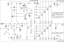
Se my attachment Schematic
for reference!
1. check all components are correctly mounted.
one component turned wrong way can destroy everything!
2. check the D5 + T4 + T5 are corrently mount
3. check D6, D7 zener are put correctly polarity!
note that zeners D6, D7 has got opposite to D5 polarity in circuit.
Cathode towards positive voltage side!
http://en.wikipedia.org/wiki/Zener_diode
4. VR1, 1 kohm, should be in middle position
5. VR2, 50R, should be put wiper FULL to R15 side!
so this trimpot is Full 50 ohm!
6. Follow the construction guide:
Final Set up And Adjustment
No attempt should be made to set up or test a power amplifier module that is not correctly mounted on
a heatsink. Make sure the main power supply is fused and the work area is clear. First check all your
work and make sure the output devices are insulated from heatsink. The set up is done without an
input or a load connected to the power amplifier.
1. Check the power supply is operating correctly and verify the rail voltages. Switch the power
supply off and check with a multimeter that the rail capacitors have discharged.
2. Using a multimeter measure the resistance of VR2 and set it for maximum resistance.
3. Correctly connect the ground lead, the two positive leads plus the negative lead to the power
amp module.
4. Remove the PCB fuses and replace with 100 ohm 5 watt resistors. Connect a multimeter that
is set to the 20 volt scale across the positive rail 100 ohm resistor.
5. Check that the power supply connections are correct one last time and switch on. If the
multimeter reading goes off-scale, turn off immediately and find the problem. Check also the
100 ohm 5 watt resistors; they may have gone open cct.
6. If everything seems ok adjust VR2 to set the output stage bias current, by measuring the
voltage across the positive rail resistor. Adjust for a reading of 4 volts per output FET pair. I.e.
For a 6 FET board set for a voltage of 12 volts. This equates to a bias current of 40mA per FET
pair or 120 mA total. For the 12 FET board set for a voltage of 24 volts.
7. If everything seems ok, check the output offset voltage and adjust VR1 to achieve an offset of
less than 10 mV. You will need to wait briefly between adjustments for the offset to settle.
8. All being well switch off, back off the bias control trimmer (VR2) and replace the 100 ohm
resistors with 10 ohm 1 watt resistors. Switch on again and re-adjust VR2 to get 0.4 volts per
FET pair.
9. Switch off, remove the resistors and put the fuses back in. Switch on, re-check the offset
voltage and adjust with VR1 if necessary.
The amp module is ready, connect the input and output and enjoy.
Attachments
hi quasi and lineup
iam ready with new fets with only 2 pairs
using the cct given
with 43.7-0-43.7 3.5 ampere aux rail tied to fet positive rail
i did everything as per your guidelines
i came up with these figures with 10 ohm resistors in both fuse holders
voltage across 10 ohm +rail resistor 0.60 volts for 2 pair of fets
with dc offset of -0.08mv
voltage across
r19-2.70 volt
r17-2.86 volts
voltages on posotivee fet
g = 3.3 volt d =42.6 volt s=0.84mv
negative fet
g= -40.3 d= -111mv s = -42.5 volts
voltages on
T8 T6 T7
e c b e c b e c b
43.4 3.3 42.2 43.4 -2.7 40.5 -2.6 -40.6 -35mv
voltage on T4 bc = 42.7 volts e = 42.2 volts
on t5 c =43.2 volt b = 42.2 volts e = 43 volts
i connected a speaker and touched the input of the amplifier it is giving a clear buzz not that clear.after that i removed the load and
inserted a fuse in negative rail leaving the 10 ohm resistor on positive rail.powered up rebiase it to 0.60 volts across the resistor dc offset of - 0.05mv everything was ok .but when i connect my speaker to it the 10 ohm resistor blew up . i removed everything
and cheked my components all was ok except 10 ohm resistor.i have checcked each and every component twice. powered it up. again i have arrived with the same problem . i have stopped everything . now you guys tell me what to do next.
thanks
ravs
Attachments
Lets wait until Quasi will reply.
Have you also those output filters:
Zobel: R42, C13
Inductor: L1
---------------------
This is only one guess:
Before you put in your fuse,
test fuse with one Multimeter in lowest OHM meter range.
Should show very low resistance value = Fuse okay.
If very high value = infinity = no contact .. then is one bad fuse.
If putting in one bad fuse = no contact, in negative
and one 10 ohm resistor in positive,
then maybe the 10 ohm resistor will burn.
When lineup said "check the zoble" he was right.. It sounds
like your amp was oscillating because The resistors blew after you connected the speaker.
#1- ,T4 mounted on one of the fins of the heatsink doesn't give enough thermal feedback and might contribute to oscillation.
You might consider drilling the hole beneath
the board like in the NMOS 350/accutrac construction guide..
#2-Try reducing R7 as you are running very low voltage for this amp (43-0-43).The lowest I've gone on a quasi is 50-0-50
with 15k for r7.
A question.. it looks like you have T4 mounted to the HS
(2 wires bc546) but Quasi mentions Q5, schematic
says Q4..wassup??
😕 😕
ravslanka said:hi quasi and lineup
iam ready with new fets with only 2 pairs
using the cct given
with 43.7-0-43.7 3.5 ampere aux rail tied to fet positive rail
i did everything as per your guidelines
i came up with these figures with 10 ohm resistors in both fuse holders
voltage across 10 ohm +rail resistor 0.60 volts for 2 pair of fets
with dc offset of -0.08mv
voltage across
r19-2.70 volt
r17-2.86 volts
voltages on posotivee fet
g = 3.3 volt d =42.6 volt s=0.84mv
negative fet
g= -40.3 d= -111mv s = -42.5 volts
voltages on
T8 T6 T7
e c b e c b e c b
43.4 3.3 42.2 43.4 -2.7 40.5 -2.6 -40.6 -35mv
voltage on T4 bc = 42.7 volts e = 42.2 volts
on t5 c =43.2 volt b = 42.2 volts e = 43 volts
i connected a speaker and touched the input of the amplifier it is giving a clear buzz not that clear.after that i removed the load and
inserted a fuse in negative rail leaving the 10 ohm resistor on positive rail.powered up rebiase it to 0.60 volts across the resistor dc offset of - 0.05mv everything was ok .but when i connect my speaker to it the 10 ohm resistor blew up . i removed everything
and cheked my components all was ok except 10 ohm resistor.i have checcked each and every component twice. powered it up. again i have arrived with the same problem . i have stopped everything . now you guys tell me what to do next.
thanks
ravs
hi lineup
thanks for your comments
i have not connected the zoble network yet
ostripper said:When lineup said "check the zoble" he was right.. It sounds
like your amp was oscillating because The resistors blew after you connected the speaker.
#1- ,T4 mounted on one of the fins of the heatsink doesn't give enough thermal feedback and might contribute to oscillation.
You might consider drilling the hole beneath
the board like in the NMOS 350/accutrac construction guide..
#2-Try reducing R7 as you are running very low voltage for this amp (43-0-43).The lowest I've gone on a quasi is 50-0-50
with 15k for r7.
A question.. it looks like you have T4 mounted to the HS
(2 wires bc546) but Quasi mentions Q5, schematic
says Q4..wassup??
😕 😕
hi ostripper
i have tried this way to for T4 mounting
http://i36.tinypic.com/90sidu.jpg
i think quasi is bit confused its t4 in the schematic
Hi Quasi I have assembled my nmos 200, feeding it with a dual of 32,5 volts, I have regulated the pot to get 300 mv with the R of 10 ohms, the problem it is that when it works it works badly at the high frequencies, other times it burns the mosfets...??? how come??? the circuit I have him revised a lot of times I have also referred the pcb but the result it is the same...help me please
- Status
- Not open for further replies.
- Home
- Amplifiers
- Solid State
- Another quasi-complementary design