I don't know the answer, but I do like the question. Thanks for bringing it out for all of us to learn from!
I found if I give a best semi-educated guess, the experts will quickly correct the error of my ways.
My thought is that it can be done, but not sure there's much to benefit unless the SPMS is just extremely noisy. My limited experience with the AmyAlice is that it works fantastically well at reducing noise as a solo circuit. Law of diminish return perhaps using two in series? Not sure if there's any significant reasons not to try it other than that.

I don't know the answer, but I do like the question. Thanks for bringing it out for all of us to learn from!
I found if I give a best semi-educated guess, the experts will quickly correct the error of my ways.
My thought is that it can be done, but not sure there's much to benefit unless the SPMS is just extremely noisy. My limited experience with the AmyAlice is that it works fantastically well at reducing noise as a solo circuit. Law of diminish return perhaps using two in series? Not sure if there's any significant reasons not to try it other than that.
Mark can chip in, but I wouldn't get close to max. We can see that when at lsat, there is a significant drop in inductance (basically becomes a resistor at dcr value with lower inductance) which changes resonant frequency as now inductance value has changed but capacitance stays the same. So dampening resistor which was calculated, doesn't do it's job as effectively if at all. Quality factor changed as well due to different BW value. So in the end you get worse filter. Parallel them for more current.
As for series, i:m about to throw a guess. Few things change. There is no dampening in that case, so it can produce unwanted frequencies. Quality factor has tendency to change, and what follows it are overshoot and possible ringing during transients. It also becomes higher order filter, which then slows transient response.
On the other hand, series (if all works well) provides better suppression of HF noise, and sharper cutoff.
let's try the answer, can be fun indeed LOL
As long as respecting the max specs the filters were designed for, I don't see a majour problem trying to run 2 filters in series, but then that's me. So worth trying.... not saying that extra filtering would bring sonic improvements though. The original filter is already a "double filter"...
On the plus side, cut off frequency remains (sadly) the same but 2 filters in series double the attenuation per decade so you get a sharper filter / even more filtering.
On the negative, you do double the losses through the filters, so the output voltage is somewhat reduced. More difficult to foresee and a feeling of mine, I would say that when daisy chaining the filters the output impedance of the resulting PS ensemble depends even more on the last filter's output cap, so that can lead to a perhaps so called "softer PS". And that may or not affect the sound.
Whatever, trying X units in series instead of 1, apart from the resulting voltage drop, shouldn't be a functional problem as long of course the max specs one filter was designed for are respected (and it should if you tried with 1 filter only). As to the sound, that's another matter: with Mark's previous PO89ZB filter there was a "hint around when daisy chaining "could" be benefical", but that was another filter and at the end IMHO what matters most is what the user hears.
That's my guess regarding the response, but no one else than Mark is best qualified for the proper response...
Have fun
Claude
Last edited:
The chain of modules includes
SMPS ----> noise filter board #1 ----> maybe board #2, maybe just wire ----> audio equipment
How good is the sound? It depends on everything in the chain. If the SMPS is truly excellent, you get good sound even with no filters at all: adding filters does nothing. On the other hand, if the SMPS is supremely terrible, two good filters in series might not be able to give good sonic results. And if the audio equipment itself is spectacularly insensitive to power supply noise, you again get good sound even with no filters at all. It depends.
The way to find out whether a certain chain of filters sounds good in your equipment is: try it yourself, and listen. Try other chains of filters too. Discover what makes you happiest. Maybe other people with other gear and other listening tastes will choose a different arrangement -- that's okay! You're just trying to get the best sound for YOU.
HOWEVER, please study the circuit schematic diagrams for PO89ZB and AmyAlice. You'll see they include resistors in series with the DC current flow. These resistors reduce the output voltage (Ohm's Law: voltage = current * resistance) which may become a problem, if the output voltage droops too low. {the series inductors also have nonzero resistance at DC and they reduce the output voltage too}
SO, I recommend that if you decide to connect "N" number of filters in series, you reduce the maximum DC current you allow to flow into the audio gear. Take the initiative to compensate for the increase in resistance, by enforcing a reduction in current. Now your final output voltage after the N-th filter in the series chain, won't droop as low.
I recommend:
- if N=1 filters are used, Max Current = 3 Amperes
- if N=2 filters are connected in series, Max Current = 2 Amperes
- if N=3 filters are connected in series, Max Current = 1 Ampere
- if N>3 filters are connected in series: DON'T DO THAT
Thank you Mark for the great explanation (to the question I raised) I had soldered 4 kits and will order more. The project is fun and rewarding and thank you for all your efforts. cheers,happy week end and God speed
You got inspired by Raspberry Pi I see 🙂 It really is better to have connections at 1, maximum 2 sides and not on all 4. Also using the very same connector for both inputs and output may be confusing. Not at first but after a while. If you use vertical USB-C PCB mount connectors and regroup all outputs at the same side and input as a horizontal version at the opposite side (or at a distance) it will be one fault possibility less.
Some members made versions with Meanwell IRM-15-5 module and mains fuse integrated which saves 1 cheap switcher, 2 connectors, cabling and clutter.
Some members made versions with Meanwell IRM-15-5 module and mains fuse integrated which saves 1 cheap switcher, 2 connectors, cabling and clutter.
1 connector/usb-c IN, 1 connector/usb-c OUT.Trying to layout w/ usb-c connector.
I will make pcbs next month and verify it.
Make some minor modifications/markings, add led indicator,
and make some cap-th available,
thx.
Attachments
Strange that AmyAlice (post #1 of this thread) uses a surface mount part for D1, while you've chosen a thru hole D1 instead. Also it appears that your layout has plenty of room to enlarge the landing pads for component leads, to make it easier to assemble and rework the board. From post #18 in this thread:
Notice how large and roomy the component footprints are, with generous extra solderpad (copper) extending way beyond the component body. This gives you more room for, um, imperfect component placement and imperfect component rotation during soldering. The extra room also allows you to touch up the board with a standard pencil soldering iron and wire solder; there's plenty of clearance and plenty of PCB copper to fit both the iron and the solder wire.
In fact, every single component on the board you see here, was soldered with a chisel tip soldering pencil and wire solder. No stencil, no solder paste, no hot plate, no hot air rework blower, no reflow oven. Just a Hakko FX-888 fitted with (this bog-standard tip) and using (this unexotic wire solder). Of course you are free to solder your AmyAlice any way you wish, and I certainly do not claim a solder pencil is better than the others. It is merely an example of a very old-school soldering method that happens to work extremely well on AmyAlice. This PCB gives you enough room to try several different soldering options. Thanks to the spacious, roomy component footprints. Wasteful? I don't think so but others may disagree.
Hi there. Any chance you'd share the gerbers for these at all?I received and stuffed some boards.
The big bipolar smps board looks great and will be a lot tidier than terminal blocks connecting 2 smps’s together and can be used with a single +0- supply. Each rail has its own fuse and filter.
I also made some 3d printed daughter board holders. It took 3 tries to get the size correct. I used PLA plastic to print them so not that strong, I wouldn’t be able to install and remove the boards too many times before it fails.
If anyone is interested in these I will post the gerbers and 3d models.
I also messed up the silkscreen on the daughter boards. I was lazy in KiCAD, just changing a reference to silkscreen and that doesn’t work. Worked that out and corrected it.
View attachment 1398021
🙂
Hello everyone,But wait, we have underestimated the attenuation. The 80 dB/decade figure doesn't include the extra attenuation provided by each of the feedthrough capacitors. Which is about 23 dB of attenuation at 100 kHz, and in excess of 60 dB at all frequencies between 7 MHz and 200 MHz. Wow. AmyAlice gets this attenuation boost twice, from the two FTCs. Also note: the 80dB/decade figure doesn't include the extra attenuation provided by the ferrite bead at the input. The bead adds further attenuation beyond about 2 MHz, see plot attached below.
I've got a problem with MCU (arduino nano) when I turn on my inverter (12.8V lifepo4 > inverter 2500w 230V).
If I calculated right, the inverter produce this noise @50kHz in the 12V DC supply path. Other 12V devices work fine.
Someone suggested AmyAlice filter, and suggested to ask here if it is good to solve my problem or could be modified to achieve my purpose.
Thanks in advance
Tired today and on the road, but had quick glance on my phone... I see roughly 500kHz (bit less than half a square which seems to be 5us, so say 2us)... and even twice that.
Says 666kHz frequency on screen, consistent with the above, could it be just that... and its double. So 0,5 to 1.5MHz to be covered?
AmyAlice would love it
Claude
Says 666kHz frequency on screen, consistent with the above, could it be just that... and its double. So 0,5 to 1.5MHz to be covered?
AmyAlice would love it
Claude
Last edited:
I have not understand why you (and DSO) calculate 666kHz from the time lenght of the peaks (so yes, less than half square so 2us) while I calculate the empty space between these noise peaks.Tired today and on the road, but had quick glance on my phone... I see roughly 500kHz (bit less than half a square which seems to be 5us, so say 2us)... and even twice that.
While switching happens at 50kHz (correct me if Im wrong) the noise is in the range of 666kHz?
I've calculated 50kHz because between peaks I see 5us x4 (a bit less, like 3.7).Says 666kHz frequency on screen, consistent with the above, could it be just that... and its double. So 0,5 to 1.5MHz to be covered?
5us x 4 = 20us > 1/20us = 50kHz
Also, i really doubt that an inverter has 666kHz switching frequency because it means:
- with 50kHz and AC out freq 50Hz the factor is 1000. So 1000 steps are used to create the sine wave, full period.
- with 666kHz the steps would be 13320, a bit crazy for an inverter to simulate a pure sine wave
I'm new to oscilloscope world so correct me if Im wrong. Thank you
Last edited:
I've got a problem with MCU (arduino nano) when I turn on my inverter (12.8V lifepo4 > inverter 2500w 230V).
If I calculated right, the inverter produce this noise @50kHz in the 12V DC supply path. Other 12V devices work fine.
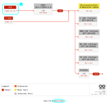
I looked at the datasheet of the Arduino Nano, and only found one place where it is legal to apply a 12V power supply. It is marked with a blue five pointed star in the attached image.
Apparently the Nano will accept any DC supply voltage between 5V and 12V. So it appears that you can install any filter (or series connection of several filters) that you wish, between your noisy 12V supply and the Arduino Nano "VIN" connector ----> as long as the voltage dropped across the filter(s) is less than about 6.5 volts. If the current flowing is the maximum allowed by the LT1117 voltage regulator on the Nano board (0.8 amperes), that means your filter(s) must have a total DC resistance, end to end, which is less than 8.1 ohms.
Attachments
Perfect analysis. I can reduce 12V to 5V by myself but even with DieNoiser LM317 regulator, the problem start when I turn on inverter. Obv, if I use 230V to 5V usb charger the MCU works as expected.Apparently the Nano will accept any DC supply voltage between 5V and 12V. So it appears that you can install any filter (or series connection of several filters) that you wish, between your noisy 12V supply and the Arduino Nano "VIN" connector ----> as long as the voltage dropped across the filter(s) is less than about 6.5 volts. If the current flowing is the maximum allowed by the LT1117 voltage regulator on the Nano board (0.8 amperes), that means your filter(s) must have a total DC resistance, end to end, which is less than 8.1 ohms.
The total load will be 30mA x 8 sensor, + 30mA per MCU + 50mA per LCD2004 display (I'm generous). So 320 mA and 20ohm.
Can you tell me which frequencies I aiming for? I really can't understand which Hz I need to suppress.
I post more useful scope screenshots
As you can see frequency vary if I zoom in time axis. But amplitude of ±1.9V RMS is the same. A bit aggressive for every kind of DC DC or regulator, if spiked at high frequencies.
To tame that someone suggested big ferrite beads on 70mmq wires that supply power to the inverter. But I'm sure that can't solve the problem.
The ripple of SMPS is, in amplitude, way smaller. For that I'm concerned. But if I have 6.5V to "sacrify" to achieve this instense-spikes noise suppression I'm confident that I can find a solution, even if is not a proper AmyAlice filter but a sort of (like PZ filter).
Thanks for help, and gratz for these designs! Have noise suppressor in this world of DCDC converters and SMPS it's a bless
- Home
- Amplifiers
- Power Supplies
- AmyAlice: DC filter for SMPS, using 2 feedthru capacitors + SMD assembly. max 3A & max 48V