The volume potentiometer in the kits is an ALPS Blue RK28 100KA, but you could use a 50k too. This is the same model used by many of the preamp projects around diy audio. Excellent quality and performance. And the diyaudio store also carries break-out boards that fit them for ease of installation.Hi!,
Is it possible to get the source of the volume button from the store kit? I built this kit, but I would like to esthetically match this component with another (original B1). Hopefully this is possible.
Thank you thomasnadeau.
I think I should have used the term: "volume knob" instead of "button". My bad... But I think I found it (as well as the ALPS since I built the kit already). Thank you again!
I think I should have used the term: "volume knob" instead of "button". My bad... But I think I found it (as well as the ALPS since I built the kit already). Thank you again!

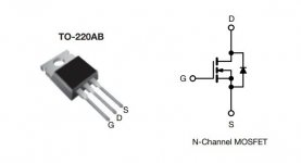
For the Jfets, I found this diagram but as I am a complete beginner with electronics, I wanted to make sure I was correct.
I connect the positive of a 9v battery to the drain. With a 100ohm resistor in between, then ground to source and to the negative of the battery? And measure voltage across the resistor? And then calculate the current? What value would be ideal?
For the IRFP610 I can use the same method?
So i was able to match the J113's. i followed the method with a 9V battery and an 100 ohm resistor, measuring across it. found values from 2.3v to 2.7v. I had 2 closely matched at 2.6V
For the IRFP 610 i dont have much luck in using the same method. dont get a reading on the DMM.
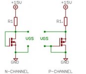
Also tried a variation on the article linked above, but as i dont have a 15V supply i used the 9V supply and the 100 ohm resistor. not sure if i do it right but if i measure the voltage between gate and source, i get a certain voltage ( i think it starts at 12mV), that is rising, but when i disconnect the supply, and reconnect, it will keep rising further on the previous voltage, so it keeps going up every time i reconnect. it also seems to measure irregurarly. i just tried one fet, cause i dont want to mess up the rest if i did something incorrect. could someone maybe explain it in a easy way how i can measure the irfp610, with the test setup i have? I have 10 610's so would like to find 4 similar ones.
9V battery, 100 ohm resistor ( i do have some more lying around, biggest one is 1.5K)
i used the diagram attached, but not sure if i did it correctly.
For the IRFP 610 i dont have much luck in using the same method. dont get a reading on the DMM.
Also tried a variation on the article linked above, but as i dont have a 15V supply i used the 9V supply and the 100 ohm resistor. not sure if i do it right but if i measure the voltage between gate and source, i get a certain voltage ( i think it starts at 12mV), that is rising, but when i disconnect the supply, and reconnect, it will keep rising further on the previous voltage, so it keeps going up every time i reconnect. it also seems to measure irregurarly. i just tried one fet, cause i dont want to mess up the rest if i did something incorrect. could someone maybe explain it in a easy way how i can measure the irfp610, with the test setup i have? I have 10 610's so would like to find 4 similar ones.
9V battery, 100 ohm resistor ( i do have some more lying around, biggest one is 1.5K)
i used the diagram attached, but not sure if i did it correctly.
Attachments
ZzerO, Please read Nelson's article that amandarae referenced again. Note that different currents for the various devices and the formula for calculating the resistor value. Use Ohm's Law to calculate the resistor values.
After reading the article, ask if you need further assistance.
After reading the article, ask if you need further assistance.
(Long-time mostly-lurker.)
I just built an ACP+, adding the small P098ZB power filter in front of the filter on the board. I'm using it as a preamp, not as a headphone amp. No hum or hiss coming out of the speakers with the volume control all the way up. I also recently bit the bullet and bought a used F7 amp, and the combination of the ACP+ and F7 (and SVS Pro 2000 subwoofer) sounds very good. The speakers are 87dB sensitive.
I was wondering if the amp/subwoofer combination would work well simply using a Y-adapter out of the preamp, and it does. I have been using a Denafrips preamp/amp combination that has two pre-outs, and runs in balanced mode, a very nice setup. The sound of the two setups is a bit different, and both are very good. The DIY Pass setup sounds a bit "smoother" or "fuller", the other setup sounds like a very good Class AB setup with a lot of power is supposed to sound.
F6 Comparison: I built an F6 last year. It sounds pretty good, too, but I like the F7 better. I think the F6 probably needs more efficient speakers to come into its own. In my setup it sounds a bit ordinary, perhaps similar to what Nelson describes about the F7 before he added the positive feedback resistor. Or maybe I'm hearing the autoformer take just a bit of the dynamic edge off?
Hello, noob here. I recently received and finished the ACP+ “naked” yesterday. the build went easy enough the parts selection sent with the kit was very nice. It powers up, I have 24v, led is lit, however I have absolutely no sound through the rca outputs or the headphone Jack. I only get a thud when powering off, ive tried different sources and cables. I’ve also noticed that both Q5 get quite warm and both Q6 stay cool. Any help figuring this thing out would be greatly appreciated.

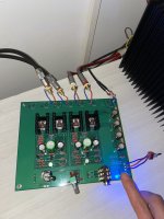
I got the acp running now. I will now start the work on the case, will have to drill the holes for mounting and the controls.
I found a smps power supply from meanwell with very low ripple noise and low leakage current. I compared a lot of models and this one had the lowest noise. I noticed that for the same voltage, power supplies with higher current ratings have higher noise levels. So I picked a 24v 0.75A model with 80mV ripple noise. Most of the 24V meanwell power supplies have 150-180mV noise.
https://www.meanwell-web.com/nl-nl/ac-dc-wall-mount-medical-adaptor-24vdc-at-0-75a-gem18i24--p1j
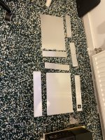
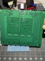
This is the case I got
It’s 330mm x 228mm x 62mm full aluminum so plenty of room to add the diy power filter later on.


Started the drilling at the back

Because the case is completely closed I think it could be beneficial to make some vents in the back and the underside? To get some heat out? Any opinions?
As for the pre amp itself, I won’t use the headphone part, so I will just use wires to bridge it.
I now used Nichicon kw audio caps for the ps filter caps but I also ordered some low esr high ripple Nichicon hw caps just in case. Would it be beneficial to use the hw caps over the audio caps in this location? Or doesn’t it matter?
I found a smps power supply from meanwell with very low ripple noise and low leakage current. I compared a lot of models and this one had the lowest noise. I noticed that for the same voltage, power supplies with higher current ratings have higher noise levels. So I picked a 24v 0.75A model with 80mV ripple noise. Most of the 24V meanwell power supplies have 150-180mV noise.
https://www.meanwell-web.com/nl-nl/ac-dc-wall-mount-medical-adaptor-24vdc-at-0-75a-gem18i24--p1j
This is the case I got
It’s 330mm x 228mm x 62mm full aluminum so plenty of room to add the diy power filter later on.
Started the drilling at the back
Because the case is completely closed I think it could be beneficial to make some vents in the back and the underside? To get some heat out? Any opinions?
As for the pre amp itself, I won’t use the headphone part, so I will just use wires to bridge it.
I now used Nichicon kw audio caps for the ps filter caps but I also ordered some low esr high ripple Nichicon hw caps just in case. Would it be beneficial to use the hw caps over the audio caps in this location? Or doesn’t it matter?
Attachments
Beautiful case! It’s going to look wonderful.
Yes, add ventilation holes so the heat can escape.
Changing the capacitors will make no difference.
If you want to upgrade something in your build, a good potentiometer or stepped attenuator would be worth consideration.
Yes, add ventilation holes so the heat can escape.
Changing the capacitors will make no difference.
If you want to upgrade something in your build, a good potentiometer or stepped attenuator would be worth consideration.
Allright, Will see if I can get some sleeves milled at work, always looks nicer than holes 😄. If not then a lot of small holes will do.
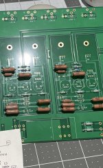
I actually have a 20K smd attenuator from eBay, the Chinese one. I soldered it in after taking pictures. Will have to listen on decent volume before marking a judgement, but it should have better channel matching for sure.
I have seen someone use film caps for C1. I have some clarity caps csa 4.7uF caps that I could use in this location. Worth trying?
Tagseim,
Sorry to hear that your ACP+ is not working.
Did you take any voltage measurements that Nelson recommended in his article?
Please measure the following DC voltages:
1. Voltage across R18
2. Voltage across R4
3. Voltage across R15
4. Voltage between test point DC1 and Ground
A picture of the bottom of the board would also be useful to check for possible issues.
Ben I appreciate the response!
i didn’t see where it mentions correct voltages for R4 and R15 in the article. Here’s what I have. I’m not sure if I’m measuring Dc1 correctly. Is it measured from ground and each point at dc1? (R12 R13)?
Here’s what I have.
R18 .4
R4 11.7
R15 10
Dc1 1.4
i didn’t see where it mentions correct voltages for R4 and R15 in the article. Here’s what I have. I’m not sure if I’m measuring Dc1 correctly. Is it measured from ground and each point at dc1? (R12 R13)?
Here’s what I have.
R18 .4
R4 11.7
R15 10
Dc1 1.4
Attachments
R12 and R13 are connected together at DC1 so either resistor lead will give the same voltage.
When stating a measurement, always include its unit of measure. I assume that your numbers are in Volts. Are the measurements the same for both channels?
Looking at the numbers there is an issue with the bias voltage to the output mosfet. Q3 is working properly, but there are issues with Q1 and Q2. Q1 has too much current through it and most likely Q2 has no current through it. So either Q2 is damaged or there is an issue with the circuit around it, or possibly Q1 is damaged (shorted).
Did you measure each resistor to verify their resistances before installing them? Looking at you picture it is hard to see the colours of R5, R6, R7. They should be 33.2K. You need to verify the resistors that you have on the board. What are the colours? You can go online and find a calculator that will convert the colours to Ohms.
Sorry, Yes I measured and sorted all resistors before installing, this is what i was given with the kit I purchased, I could hardly get most of them to fit. I kinda feel like I just wasted $200. I built the ACA a couple months and it worked perfectly.
- Home
- Amplifiers
- Pass Labs
- Amp Camp Pre+Headphone Amp - ACP+