I liked the sound of the naked ACP+ enough to convince myself a remote controlled, linear power supply implementation was sensible.🙃
Bought the chassis last year in Gianluca’s Black Friday sale and the boards and J74’s from the Store. Rest of the parts from Mouser and Newark. Took a chance and bought only 20 J113’s but I got an identical (to 3 decimal points) matched pair and two other good enough matches out of the 20. Was lucky I guess.
I had the donuts but it was a close thing with the 1U height and the potential for a short so I used a nylon nut and bolt. The paint Modushop uses on these chassis is tough - took effort to scrape it to metal for the grounds.
Academy Audio’s VCX kit provided the volume control, display and remote control. The extended time to get parts onto this rock meant I had time to engrave, drill and Dremel the panels. A couple of laser-cut perspex pieces made the positioning of the display ‘adjustable’ to compensate for any ‘outs’ by me. Still have to label the rear panel.
I implemented two inputs, two outputs and a tape monitor to cover all bases. It sound great - thanks again Papa!

Fugly!

re Modu scraping-for-gnd: just tighten all screws properly, entire case is one piece electrically
re Modu scraping-for-gnd: just tighten all screws properly, entire case is one piece electrically
Thanks, ZM. I tried that and couldn’t get continuity between chassis and the ACP+ until I scraped that paint!! Even used star washers as you can see. So, to be safe….I defaced Gianluca’s chassis 🙃!
I had the same experience as @derekr, building a Noir headphone amp in a 1U ModuShop Galaxy chassis. To expose the bare metal, I used sandpaper, which took a couple minutes.
I finally finished reading all 114 pages in this thread and can post something 🙂
I was looking for a discrete class A headphone amp and I dont know why I only recently learned about ACP+ since I also have eyes on a HPA-1 for some time. So I purchased the kit with the parts two weeks ago I think, and I have received them just yesterday and I have built the amp immediately (before reading this thread). Mainly I had no issues, I am not very experienced on soldering but also not novice, there is no difficulty on building the kit. After the build, the test voltages measure OK and the amp works fine, and even with direct iPhone output it sounds great. Here are some additional comments and a few questions I have not seen in this thread.
Regarding to the parts that comes with the kit, and I saw it is mentioned a few months ago here, that due to availability issues the resistors sent are larger. This was a bit confusing at first but no big issue. Also, the C3 capacitor is not marked "gold", and again it is not an issue but it is confusing because the BOM sent with the kit mentions it is gold marked, and there is another cap with the same value so again confusing to figure out which one to use. So my feedback would be that it can be a good thing to at least add a small note to the parts kit mentioning these two points. After ~30 minutes, I measure DC points as 10.89V and 10.74V and V(R4) as 1.207V and 1.225V. I think it can also be a good idea to strongly suggest to measure the value of R4s to the best you can before soldering, so the actual current can be calculated afterwards.
At the moment I am powering the amp with a bench supply (24V, limited to 500mA). Usually at the very beginning, it goes red (passes 500mA) very briefly and then works normally. I tried increasing it to 1.4A (maximum the supply can), and it is still the same. I guess it is a transient/in-rush at start, what is the exact reason for this ?
I have read it is fine to use 10K or 50K volume pot as long as it is fine for the source. I actually have a preamp (which probably I will keep) so I do not need the volume pot on ACP+. I know I can just leave it there and keep it at max or close to max, but out of curiosity, can I just remove it and short the RCA input to the amp input (R1) or do I need a parallel resistor (~20K) to GND like the volume pot ?
I also may want to remove the input selector, so just use one input and directly connect it.
I will probably use the amp with 55ohm headphones. I read about impedance matching and I can add the required resistor in parallel, but I wonder if this would have an effect on the distortion/noise etc. profile of the amp ? (theoretically)
I do not need the preamp (RCA) out (I dont have power amps or speakers). Just for the sake of simplification, would it be OK to remove the resistors (R16,R17), RCA outs and use a normal TRS socket ? Does the amp need to be terminated with a load always ?
Also, at least for the sake of convenience, I may want to add a balanced headphone output, 4 pin XLR, and would like to do the same as Benchmark does in their amp, connect L- and R- to the ground of the respective channels. I guess that would work fine ?
As far as I understand the input is a differential amp with one input coming from RCA and the other is the feedback from the output. I guess it is not straight-forward to make this accept a balanced signal ? or is it as simple as connecting balanced (-) input where the feedback is connected (I saw the schematic here with a balanced attenuator) ?
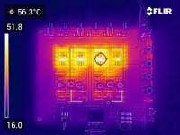
I did not check anything yet other than seeing ~60C temperature on mosfets, but I wonder if the cooling can be accomplished with thermal vias by the PCB. I think I havent seen a thermal image of the amp, so here is one attached.
I was looking for a discrete class A headphone amp and I dont know why I only recently learned about ACP+ since I also have eyes on a HPA-1 for some time. So I purchased the kit with the parts two weeks ago I think, and I have received them just yesterday and I have built the amp immediately (before reading this thread). Mainly I had no issues, I am not very experienced on soldering but also not novice, there is no difficulty on building the kit. After the build, the test voltages measure OK and the amp works fine, and even with direct iPhone output it sounds great. Here are some additional comments and a few questions I have not seen in this thread.
Regarding to the parts that comes with the kit, and I saw it is mentioned a few months ago here, that due to availability issues the resistors sent are larger. This was a bit confusing at first but no big issue. Also, the C3 capacitor is not marked "gold", and again it is not an issue but it is confusing because the BOM sent with the kit mentions it is gold marked, and there is another cap with the same value so again confusing to figure out which one to use. So my feedback would be that it can be a good thing to at least add a small note to the parts kit mentioning these two points. After ~30 minutes, I measure DC points as 10.89V and 10.74V and V(R4) as 1.207V and 1.225V. I think it can also be a good idea to strongly suggest to measure the value of R4s to the best you can before soldering, so the actual current can be calculated afterwards.
At the moment I am powering the amp with a bench supply (24V, limited to 500mA). Usually at the very beginning, it goes red (passes 500mA) very briefly and then works normally. I tried increasing it to 1.4A (maximum the supply can), and it is still the same. I guess it is a transient/in-rush at start, what is the exact reason for this ?
I have read it is fine to use 10K or 50K volume pot as long as it is fine for the source. I actually have a preamp (which probably I will keep) so I do not need the volume pot on ACP+. I know I can just leave it there and keep it at max or close to max, but out of curiosity, can I just remove it and short the RCA input to the amp input (R1) or do I need a parallel resistor (~20K) to GND like the volume pot ?
I also may want to remove the input selector, so just use one input and directly connect it.
I will probably use the amp with 55ohm headphones. I read about impedance matching and I can add the required resistor in parallel, but I wonder if this would have an effect on the distortion/noise etc. profile of the amp ? (theoretically)
I do not need the preamp (RCA) out (I dont have power amps or speakers). Just for the sake of simplification, would it be OK to remove the resistors (R16,R17), RCA outs and use a normal TRS socket ? Does the amp need to be terminated with a load always ?
Also, at least for the sake of convenience, I may want to add a balanced headphone output, 4 pin XLR, and would like to do the same as Benchmark does in their amp, connect L- and R- to the ground of the respective channels. I guess that would work fine ?
As far as I understand the input is a differential amp with one input coming from RCA and the other is the feedback from the output. I guess it is not straight-forward to make this accept a balanced signal ? or is it as simple as connecting balanced (-) input where the feedback is connected (I saw the schematic here with a balanced attenuator) ?
I did not check anything yet other than seeing ~60C temperature on mosfets, but I wonder if the cooling can be accomplished with thermal vias by the PCB. I think I havent seen a thermal image of the amp, so here is one attached.
Attachments
Last edited:
Hi Mete,
Best, Walter
- The reason for the big startup current are the 1000uF elco's C6 - C9. you are loading them with a 1 Ohm resistor, 24 volts, so do the Ohm's law.
- Nelson says the amp is build with the best performance at 32 Ohms. So putting a 82 Ohms resistor in parallel with your headphones will give the right result.
- I think it needs to be terminated with a load, because for use as a preamp Nelson put in 2 x 33.2 Ohms resistors. A connecting power amp normally has a too high input impedance to let the ACP+ perform at it best.
- Don't know what you mean with the balanced headphone output and 4pin XLR? It is single ended all the way.
- To make the input balanced you connect the '- input' to the gate of Q2 with a resistor. But then it isn't really nice the same as the '+input'. So have a look at my schematic in post #2245.
- Thanks for the thermal image, the sinks get hotter than expected, This give me no room for more voltage or current with these sinks....
Best, Walter
Last edited:
Thanks @WalterW
(I cant quote the post for some reason. maybe because I just registered)
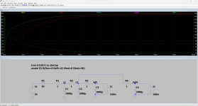
Right, it seems ~20A might be needed, I did a simple spice sim. Is this the reason of the problem with some SMPS units ?
I know ACP+ is single ended, what I mean is just for convenience (I have balanced amps as well) to have a balanced headphone connector in addition to TRS. Benchmark says here: "... this connector is not driven with a voltage-balanced signal. Instead, it provides isolated left and right ground returns that are individually connected to the ground reference points in the left and right amplifiers.... ". So I was thinking to do the same.
Regarding balanced input, when you say "But then it isn't really nice the same as the '+input'.", you mean the performance is not the same ?
(I cant quote the post for some reason. maybe because I just registered)
Right, it seems ~20A might be needed, I did a simple spice sim. Is this the reason of the problem with some SMPS units ?
I know ACP+ is single ended, what I mean is just for convenience (I have balanced amps as well) to have a balanced headphone connector in addition to TRS. Benchmark says here: "... this connector is not driven with a voltage-balanced signal. Instead, it provides isolated left and right ground returns that are individually connected to the ground reference points in the left and right amplifiers.... ". So I was thinking to do the same.
Regarding balanced input, when you say "But then it isn't really nice the same as the '+input'.", you mean the performance is not the same ?
For those who may wonder, the spice simulations for unlimited (50A) power supply current and a realistic (500mA) one. I am not sure if I am doing the load side right, but I just added 160mA current sinks to each channel.
Attachments

Haha, didn't know Benchmark is an audio-manufacturer, thought it was someone here with that name 😛
Ofcourse you can connect it that way, a 4P XLR gives much better connection than a TRS.
Or use the Swiss made Lemo connectors, that some guys here use: EGG.3B.304.CLL
About balanced in: I mean this part connected to the gate of Q1 is not exactly the same as the part connected to the gate of Q2.

Ofcourse you can connect it that way, a 4P XLR gives much better connection than a TRS.
Or use the Swiss made Lemo connectors, that some guys here use: EGG.3B.304.CLL
About balanced in: I mean this part connected to the gate of Q1 is not exactly the same as the part connected to the gate of Q2.
If I can change the input signal level, what is the best position of the volume pot ? Maximum ? or as long as it is at more than 50% is it better to maximize the input signal and adjust the volume with ACP+ ?
After a long, dark covid period, I'm back 🙂
What a nice preamp this is, it has a lot of potential.
My goal is to pimp this ACP+ just like Patrick, EUVL mentioned: with dual rails, no in and output capacitors, linear regulated quality PSU, balanced and single ended inputs, balanced Muse attenuator or a 4-gang motorised Alps potmeter, passive cross feed and a nice casing, probably the Galaxy 330-280 from Modushop with nice machined frontplate.
I build it two times as a matching preamp / HPA for my kids VFET pt2 amplifiers. I have all the time, kids won't be leaving the house soon, because of the shortage of houses in the Netherlands.
Maybe I should open a new thread for this?
Any advice on the balanced Muse attenuator? Is there anywhere a current open thread for this? Where to buy PCB's?
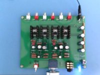
The schematic I made, is a mix of the BA1 frontend, the J2 and this ACP+.
I made on experimental board first the original version and rebuild it to the schematic below, all works fine, output offset of the original was from 40mV to zero in few minutes, this version is from 10mv to zero in a few minutes. Maybe I'll experiment with a simple servo to keep it at 0 volts at the output.
JFET's are 10.0mA 2SK170BL and two perfectly matched 2SJ74BL's of 8.3mA. I will be playing with the 3 specified output transistors. And maybe degeneration of them, that's why I put in the 0 Ohm resistor.
View attachment 1155501
View attachment 1155509
Very nice. Dual rails, no sound-coupling capacitors and liner power supplies are mandatory requirements in my book.
Muse attenuators??? well, a quick peek at the pdf has revealed two sound coupling caps per channel.. so... an instant pass. I had very good results with stepped attenuators... ELNA 23-step switches and carbon-film resistors. Relay arrays are also good.... but I prefer a stepped attenuator because I have more control over switch contacts and resistor choices.
The best would be to forget about volume attenuation inside the amp, and use a source to control the volume... if possible, of course.
If you’re referring to the Academy Audio version of the Muse volume control the two coupling caps are optional - i.e they’re not on the PCB, you have the option to add them. It’s detailed in the Manual/App Note.
Very nice. Dual rails, no sound-coupling capacitors and liner power supplies are mandatory requirements in my book.
Why dual rails over a single rail linear supply in something like the ACP+?
Thanks
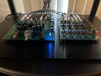
I liked the sound of the naked ACP+ enough to convince myself a remote controlled, linear power supply implementation was sensible.🙃
Bought the chassis last year in Gianluca’s Black Friday sale and the boards and J74’s from the Store. Rest of the parts from Mouser and Newark. Took a chance and bought only 20 J113’s but I got an identical (to 3 decimal points) matched pair and two other good enough matches out of the 20. Was lucky I guess.
I had the donuts but it was a close thing with the 1U height and the potential for a short so I used a nylon nut and bolt. The paint Modushop uses on these chassis is tough - took effort to scrape it to metal for the grounds.
Academy Audio’s VCX kit provided the volume control, display and remote control. The extended time to get parts onto this rock meant I had time to engrave, drill and Dremel the panels. A couple of laser-cut perspex pieces made the positioning of the display ‘adjustable’ to compensate for any ‘outs’ by me. Still have to label the rear panel.
I implemented two inputs, two outputs and a tape monitor to cover all bases. It sound great - thanks again Papa!
View attachment 1168910View attachment 1168911View attachment 1168912
I’m new to the hobby so please excuse my lack of knowledge. I just recently finished building an acp+ and the 6-24 crossover. All thanks go to Nelson Pass for designing such great devices and to 6l6 for providing assembly instructions that were easy enough for an old fart like me to build them. With those successes under my belt I thought I’d like to try installing the Muses volume control setup. I’m probably in over my head in figuring out how to provide +/-15v while using the 24v wall watt to power the preamp. Should I use a separate power supply to drive the Muses or can it be driven by the 24v wall wart?
Attachments
- Home
- Amplifiers
- Pass Labs
- Amp Camp Pre+Headphone Amp - ACP+