So building my ACP+ this week and I'm a rookie. When I picked up my kit I bought 3 of the SMPS filter kits to practice my soldering. I think I got through those pretty well. The ACP+ board is quite different. I know some of the parts get soldered from the back. But thould all the parts be soldered from the back side? I also have the DIYAudio store solder roll and its very thin for some of the larger board openings....still good to use ? Finally, the caps seem to vary in color from one kit to the next....normal?
Yes, all the parts get soldered from the back. ...but so does everything on the filter board.
The Fire-Metall solder is the best solder I have ever used and appropriate for all electronics.
Yes. Supply chains in electronics are utterly screwed up and the parts are changing from batch to batch. Everything supplied, regardless of specific part/manufacturer/etc… is of quality that we are happy to listen to ourselves and stand behind.

Definitely follow Jim's advice on the solder - where has Richard's solder been all my life?! And yes, as Jim said, all the components are soldered to one side of the PCB. Theres nothing to solder onto the ground plane board - you just use the supplied screws and nylon spacer to set them apart, but they are connected via the screws. The parts indeed vary from each run of the kits just like many others do, simply because of parts supply availability. We've worked hard to source all of the parts for this kit using high quality components that also meet the minimum specification Nelson's article set the bar for. If you have any questions about parts or putting the kit together, post here or DM me. Always happy to help.
--Tom
--Tom
A while back @6L6 posted on building his ACP+ into a chassis here: https://www.diyaudio.com/community/threads/amp-camp-pre-headphone-amp-acp.344836/page-107
A bit before that I'd helped my friend Gary build his own ACP+ and posted pix here: https://www.diyaudio.com/community/...eadphone-amp-acp.344836/page-108#post-7149028
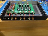
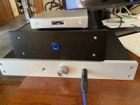
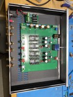
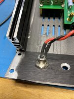
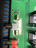
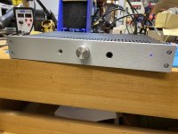
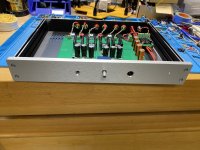
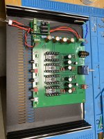
After Gary had taken a couple of months to listen to his ACP+ he decided he really liked it but wanted it in a more lets say, less accident-prone form factor for his daily desk, so he went ahead and purchased the same chassis 6L6 used. Last weekend I helped him fabricate the chassis and stuff the ACP+ in there. Like Jim's build, I also included an SMPS DC Filter kit (p089zb) on the DC power inlet. I can report that the build was very straight-forward. I (re)discovered that Nelson left 2 extra +/- holes next to each RCA, so for all of the I/O (the RCAs) there is no need to remove them from the board to solder in fly wires; just connect those and leave the board-mounted ones as-is. If you look, I used euro blocks/phenix connectors to make connecting things easier but also easier to remote/experiment with in the future. As you can see, I mounted the board with all of its board-mounted front panel components right to the front panel except for the LED which I used a fly wire to mount elsewhere. We mounted the power switch off board on the rear panel of the chassis again via fly wires.
I've had it sitting on my desk all day listening to it on my AKG712pros and its really fantastic. Quiet as can be with loads of dynamics and detail as we've come to expect from Nelson's awesome creations.
Enjoy!
--Tom
A bit before that I'd helped my friend Gary build his own ACP+ and posted pix here: https://www.diyaudio.com/community/...eadphone-amp-acp.344836/page-108#post-7149028
After Gary had taken a couple of months to listen to his ACP+ he decided he really liked it but wanted it in a more lets say, less accident-prone form factor for his daily desk, so he went ahead and purchased the same chassis 6L6 used. Last weekend I helped him fabricate the chassis and stuff the ACP+ in there. Like Jim's build, I also included an SMPS DC Filter kit (p089zb) on the DC power inlet. I can report that the build was very straight-forward. I (re)discovered that Nelson left 2 extra +/- holes next to each RCA, so for all of the I/O (the RCAs) there is no need to remove them from the board to solder in fly wires; just connect those and leave the board-mounted ones as-is. If you look, I used euro blocks/phenix connectors to make connecting things easier but also easier to remote/experiment with in the future. As you can see, I mounted the board with all of its board-mounted front panel components right to the front panel except for the LED which I used a fly wire to mount elsewhere. We mounted the power switch off board on the rear panel of the chassis again via fly wires.
I've had it sitting on my desk all day listening to it on my AKG712pros and its really fantastic. Quiet as can be with loads of dynamics and detail as we've come to expect from Nelson's awesome creations.
Enjoy!
--Tom
Attachments
-
 IMG_4742.jpeg523 KB · Views: 304
 -
 IMG_4747.jpeg492.7 KB · Views: 288
 -
 IMG_4734.jpeg719.9 KB · Views: 270
 -
 IMG_4736.jpeg448.4 KB · Views: 257
 -
 69663427538__19B726ED-40C0-4BE1-8B53-53B571DC0B45.jpeg474.2 KB · Views: 248
 -
 IMG_4744.jpeg528.8 KB · Views: 273
 -
 IMG_4743.jpeg527.2 KB · Views: 272
 -
 IMG_4739.jpeg797.9 KB · Views: 298
Appreciate it Tom. I've been practicing my soldering on a set of speaker crossovers and I've gotten pretty comfortable with getting a good solder. On to the ACP+Definitely follow Jim's advice on the solder - where has Richard's solder been all my life?! And yes, as Jim said, all the components are soldered to one side of the PCB. Theres nothing to solder onto the ground plane board - you just use the supplied screws and nylon spacer to set them apart, but they are connected via the screws. The parts indeed vary from each run of the kits just like many others do, simply because of parts supply availability. We've worked hard to source all of the parts for this kit using high quality components that also meet the minimum specification Nelson's article set the bar for. If you have any questions about parts or putting the kit together, post here or DM me. Always happy to help.
--Tom
I like this idea. If I wanted to do this are there changes I should incorporate before I build my ACP+? I have a couple ACA's and looking to build a 2 channel systemA while back @6L6 posted on building his ACP+ into a chassis here: https://www.diyaudio.com/community/threads/amp-camp-pre-headphone-amp-acp.344836/page-107
A bit before that I'd helped my friend Gary build his own ACP+ and posted pix here: https://www.diyaudio.com/community/...eadphone-amp-acp.344836/page-108#post-7149028
After Gary had taken a couple of months to listen to his ACP+ he decided he really liked it but wanted it in a more lets say, less accident-prone form factor for his daily desk, so he went ahead and purchased the same chassis 6L6 used. Last weekend I helped him fabricate the chassis and stuff the ACP+ in there. Like Jim's build, I also included an SMPS DC Filter kit (p089zb) on the DC power inlet. I can report that the build was very straight-forward. I (re)discovered that Nelson left 2 extra +/- holes next to each RCA, so for all of the I/O (the RCAs) there is no need to remove them from the board to solder in fly wires; just connect those and leave the board-mounted ones as-is. If you look, I used euro blocks/phenix connectors to make connecting things easier but also easier to remote/experiment with in the future. As you can see, I mounted the board with all of its board-mounted front panel components right to the front panel except for the LED which I used a fly wire to mount elsewhere. We mounted the power switch off board on the rear panel of the chassis again via fly wires.
I've had it sitting on my desk all day listening to it on my AKG712pros and its really fantastic. Quiet as can be with loads of dynamics and detail as we've come to expect from Nelson's awesome creations.
Enjoy!
--Tom
Exactly. Do yourself a favor and don't board-mount any of the I/O or controls. On the built i showed, @g262isaud and I had built the ACP+ in its "stock" setup he used it that way for a few months until wanting to put it into a case, and in that case it is far easier to leave at least the front panel-mounted components as is and mount them thru the front panel.
But if i were to start from scratch, I would probably leave them off because its just less constrained to be able to mount them wherever on the front panel versus exactly where they have to be due to board mounting. Also for newbies or folks that want to experiment, I also recommend use of euroblocks anyways as that allows for easy insert/removal of the entire board, parts swaps or general fat fingering which I am guilty of too many times. like on this build I first swapped the + and - on the rear RCAs and had to fix that. Because I had euroblocks on the board, I just unscrewed the blocks, flipped the wires and put them back. No fuss, no muss. 😉
--tom
I forgot to tag Gary's UID on this post @g262isaudA while back @6L6 posted on building his ACP+ into a chassis here: https://www.diyaudio.com/community/threads/amp-camp-pre-headphone-amp-acp.344836/page-107
A bit before that I'd helped my friend Gary build his own ACP+ and posted pix here: https://www.diyaudio.com/community/...eadphone-amp-acp.344836/page-108#post-7149028
After Gary had taken a couple of months to listen to his ACP+ he decided he really liked it but wanted it in a more lets say, less accident-prone form factor for his daily desk, so he went ahead and purchased the same chassis 6L6 used. Last weekend I helped him fabricate the chassis and stuff the ACP+ in there. Like Jim's build, I also included an SMPS DC Filter kit (p089zb) on the DC power inlet. I can report that the build was very straight-forward. I (re)discovered that Nelson left 2 extra +/- holes next to each RCA, so for all of the I/O (the RCAs) there is no need to remove them from the board to solder in fly wires; just connect those and leave the board-mounted ones as-is. If you look, I used euro blocks/phenix connectors to make connecting things easier but also easier to remote/experiment with in the future. As you can see, I mounted the board with all of its board-mounted front panel components right to the front panel except for the LED which I used a fly wire to mount elsewhere. We mounted the power switch off board on the rear panel of the chassis again via fly wires.
I've had it sitting on my desk all day listening to it on my AKG712pros and its really fantastic. Quiet as can be with loads of dynamics and detail as we've come to expect from Nelson's awesome creations.
Enjoy!
--Tom
Ah good point. As you can see I mounted the DPDT switch on the PCB and thru the front panel but its not attached to the front panel with a nut because its not that type. Same with the volume pot and headphone jack. These are all actually mounted to the PCB which is standoff-mounted to the bottom of the case. Think ahead or prepare to drill many times. 😉Don’t connect the jacks, switch, or pot to the PCB. This way you’ll be able to mount them exactly where you want on the chassis. You may need a different DPDT switch that is panel mount.
As a general matter, I wish the all signal input-output and power (AC and DC) connections/pads on DIY PCBs have the option of adding Euroblock or Faston connectors.
In addition, it would be helpful if the BOM and/or text would state the pin-to-pin distance for pads that support Euroblocks (e.g., 5 mm) and perhaps a suggested part no. from one of the manufacturers like Molex.
In addition, it would be helpful if the BOM and/or text would state the pin-to-pin distance for pads that support Euroblocks (e.g., 5 mm) and perhaps a suggested part no. from one of the manufacturers like Molex.
Definitely on the modular connectors. It really adds to the flexibility of experimentation later, and also keeps you from inadvertently breaking things if you do have to take something out of the case or re-do some work. Having them in place allows you to swap out the entire PCB for other projects without having to build another case is considerable. I usually only go back and permanently solder the positions I used the blocks on after I've listened to something for a while and really enjoy it, otherwise I leave it because its likely a chassis to use on a future project. There are only a few of these in my collection. 😉
As for the lead spacing in the BOM, thats a fantastic idea as is creating multi-hole options to support different size options on the PCB. For example, the same capacitor value in a higher voltage rating is more often than not, a larger package as well as having different lead spacing and even lead diameters (i.e.: thicker). Unfortunately thats really only up to the designers of the projects so they'll have to keep this in mind. However, in leu of connectors coming with kits/projects, I keep several boxes of assorted spacing sizes in doubles and triples. These are pretty inexpensive. Check out the various suppliers including amzn for the assortments. Unless you know you need a decent quantity of a particular spacing/size, thats the more economical way to go. I do the same with shrink wrap tubing as you can get a myriad of diameters and colors in the same box.
Cheers!
--Tom
Well I was cruising along pretty well on ACP+ build until I got to the end of the resistors and realized I was missing 3 of the 1 ohm, 3 watt resistors. Will any similar spec'd resistors work? Any suggestion where to get them? Beyond that I had to learn a bunch more than anticipated. Thought I could just color match from images on the build by 6L6 but many of the parts are different so I had to learn how to read the printed ones and test the non-printed ones.
It was a store kit. I got one of the 1 ohm resistors. I've torn the packaging apart trying to find them but don't think they ever made it into the packaging.
Hi!,
Is it possible to get the source of the volume button from the store kit? I built this kit, but I would like to esthetically match this component with another (original B1). Hopefully this is possible.
Is it possible to get the source of the volume button from the store kit? I built this kit, but I would like to esthetically match this component with another (original B1). Hopefully this is possible.
going trough my mouser order i found that i ordered 1/4watt 33.2ohm resistors for positions R16 and R17 instead of 400mW. Am i safe to use the 250mW ones?
- Home
- Amplifiers
- Pass Labs
- Amp Camp Pre+Headphone Amp - ACP+