Hello wg45,
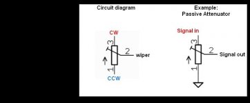
cw = clockwise = right turn of the pot
ccw = counterclockwise = left turn of the pot
w = wiper.
Cheers
Dirk 😉
cw = clockwise = right turn of the pot
ccw = counterclockwise = left turn of the pot
w = wiper.
Cheers
Dirk 😉
Thanks for clearing up the mystery, Dirk.Hello wg45,
cw = clockwise = right turn of the pot
ccw = counterclockwise = left turn of the pot
w = wiper.
Cheers
Dirk 😉
As a follow up, why would you need a clockwise and a counterclockwise connection? I can imagine that a volume pot might turn in either direction but why would a specific input be needed?
You want your volume-pot acting from turned completely left= ccw (=silence = high resistance for audio signal / low resistance to ground) to fully turned right = cw (= full volume = low resistance for audio signal from input to wiper out / high resistance from wiper to ground).
You can change that into the opposite direction.
You could also use the trimpot as a variable resistor inline the audio signal without shunting it to ground.
Cheers
Dirk
You can change that into the opposite direction.
You could also use the trimpot as a variable resistor inline the audio signal without shunting it to ground.
Cheers
Dirk
Attachments

is used on trimmer .....Thanks for clearing up the mystery, Dirk.
As a follow up, why would you need a clockwise and a counterclockwise connection? I can imagine that a volume pot might turn in either direction but why would a specific input be needed?
can smile a bit like dx steering wheel in uk 🙂You want your volume-pot acting from turned completely left= ccw (=silence = high resistance for audio signal / low resistance to ground) to fully turned right = cw (= full volume = low resistance for audio signal from input to wiper out / high resistance from wiper to ground).
You can change that into the opposite direction.
You could also use the trimpot as a variable resistor inline the audio signal without shunting it to ground.
Cheers
Dirk
Usually you want the pot to increase the value with a clockwise rotation. Think of a volume knob.As a follow up, why would you need a clockwise and a counterclockwise connection? I can imagine that a volume pot might turn in either direction but why would a specific input be needed?
Hey y’all, so this is the first time this has happened to me. I’ve been using this for about a week when suddenly I lost a couple resistors. Still not sure how it happened. I have a couple back ups I’m about to put in, but I wanted to see what the proper procedure is before popping them back in here to ensure there’s no further issues. I’ve got the picture as is after the failure and one showing it cleaned up. At first I thought there was solder that wasn’t getting wicked up but now I think it’s the pcb having gotten removed in that area. Thanks!


What on earth happened to roast those resistors?
Figure out the failure mode before replacing them...
Figure out the failure mode before replacing them...
Yeah, I’m trying to figure that out. The voltage matches from the left side of the board to the right side at that node. I’m not quite sure where to proceed from there.What on earth happened to roast those resistors?
Figure out the failure mode before replacing them...
I should note that I put in new resistors in that spot to test the voltages with, turning them on and then off as soon as the voltage reading stabilizedYeah, I’m trying to figure that out. The voltage matches from the left side of the board to the right side at that node. I’m not quite sure where to proceed from there.
Well it looks like I’m no longer drawing .3V at R18 but .8V. Maybe there’s a short somewhere.What on earth happened to roast those resistors?
Figure out the failure mode before replacing them...
Too much current, so toasted resistors.
R9, R11, Q4, and Q5 set the current, so those need checking.
R9, R11, Q4, and Q5 set the current, so those need checking.
I checked R9 and R10 and they were fine. I’m not really sure how to check Q4 or Q5Too much current, so toasted resistors.
R9, R11, Q4, and Q5 set the current, so those need checking.
I don't know how to check an optocoupler. What I usually do on my projects with ICs is to mount them on sockets. I also purchase more than I need of the ICs and Mosfets, especially when they are not expensive, so that I have spares on hand. Then I would do a swap as a test.
As for the mosfet, you can remove it and check it with a tester if you have one, or you can internet search for procedures for simple tests with a multimeter.
Edit: I just Googled "How to test an optocoupler" and there were a lot of hits.
As for the mosfet, you can remove it and check it with a tester if you have one, or you can internet search for procedures for simple tests with a multimeter.
Edit: I just Googled "How to test an optocoupler" and there were a lot of hits.
I see microfractures... check the white arrows. Always mount the transistors on the heatsink & tighten them first, and then solder them.
Also, a lot of solder leftovers - blue arrows... dare to show us the underside?

Also, a lot of solder leftovers - blue arrows... dare to show us the underside?
Thanks for the feedback, sure!

Also, a lot of solder leftovers - blue arrows... dare to show us the underside?
ahaiden,Thanks for the feedback, sure!
i think you need a lot of practice soldering components to a PCB - a lot of potential dry joints, a lot of too much solder on the pads or not enough. plus some of the comp legs are not trimmed properly
not sure what equipment you use but you need a temp controlled soldering station with a number of different size tips
ideally your tip temp should be 300 - 350 C but you need to learn to select the right size tip for the pads and components because the trick is to solder in the quickest possible way at the right temp, so for example for a thicker pad or comp leg you need a larger tip and so on.
i personally use a kind of universal chisel tip @350C for almost all of my work but i have 30 odd years of experience plus being trained to do military grade soldering.
so in short practice makes a big difference and the right tools help make the entire work easier.
as a final note - do not use lead free solder, it has compelety different requirements, 60/40 tin lead or 60/35/5 tin lead copper is all you need
Thanks! Yeah I’m definitely realizing that I need more than just the single tip that it came with. I also need the right clippers for the job as mine can’t get very close to the board to trim with. The right tools make a massive differenceahaiden,
i think you need a lot of practice soldering components to a PCB - a lot of potential dry joints, a lot of too much solder on the pads or not enough. plus some of the comp legs are not trimmed properly
not sure what equipment you use but you need a temp controlled soldering station with a number of different size tips
ideally your tip temp should be 300 - 350 C but you need to learn to select the right size tip for the pads and components because the trick is to solder in the quickest possible way at the right temp, so for example for a thicker pad or comp leg you need a larger tip and so on.
i personally use a kind of universal chisel tip @350C for almost all of my work but i have 30 odd years of experience plus being trained to do military grade soldering.
so in short practice makes a big difference and the right tools help make the entire work easier.
as a final note - do not use lead free solder, it has compelety different requirements, 60/40 tin lead or 60/35/5 tin lead copper is all you need
Thanks! Yeah I’m definitely realizing that I need more than just the single tip that it came with. I also need the right clippers for the job as mine can’t get very close to the board to trim with. The right tools make a massive difference
I'm in the same boat as you are, with technique. I'm very rusty.
I have been thinking of retiring and taking a simple course at the local community college.
But even so, the people in this forum have me beat... building these things takes a lot more than just understanding the schematics, knowing how to solder, having the right tools and time... it's also the experience to tweak them and troubleshooting them.
- Home
- Amplifiers
- Pass Labs
- Amp Camp Pre+Headphone Amp - ACP+