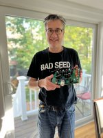
Since it was BA2022 last weekend and I couldn't make it, I decided to sit down with a friend and do a mini-BA22 NH edition with my friend Gary. We successfully built a ACP+ and it sounds great. Another successful DIYer has caught the bug.
Thanks again Papa for a project that is super accessible for newbies. 🙂
Thanks again Papa for a project that is super accessible for newbies. 🙂
Attachments


Something odd happened today....
I had no music running, but the ACP+ and NAD 326 were on. Out of the blue the system started to make a static noise and the amp went into protection, but the buzzing continued even after the amp was off.
It did not matter which input was selected.
I unplugged everything and popped the top.
I measured .8 volts, AC on the output, although the sound seemed louder on the left channel. I unplugged the ACT+ very quickly, so my perception might be off here.
I have 24v coming in.
At R18 I measure .345v DC.
At DC1 both channels are at 10.75v.
Now that I have powered the unit on and off, I am back down to 0v, AC on the output.
All of my RCAs were properly seated, as was the power input.
Nothing looks amiss under the hood.
Anybody have any idea why this would happen?
Last edited:
Have you tried just the acp+ not connected to anything? I would ellimaged the NAD and work back from there. Do you get power? audio in headphone output?Something odd happened today....
I had no music running, but the ACP+ and NAD 326 were on. Out of the blue the system started to make a static noise and the amp went into protection, but the buzzing continued even after the amp was off.
It did not matter which input was selected.
I unplugged everything and popped the top.
I measured .8 volts, AC on the output, although the sound seemed louder on the left channel. I unplugged the ACT+ very quickly, so my perception might be off here.
I have 24v coming in.
At R18 I measure .345v DC.
At DC1 both channels are at 10.75v.
Now that I have powered the unit on and off, I am back down to 0v, AC on the output.
All of my RCAs were properly seated, as was the power input.
Nothing looks amiss under the hood.
Anybody have any idea why this would happen?
tom
Have you tried just the acp+ not connected to anything? I would ellimaged the NAD and work back from there. Do you get power? audio in headphone output?
tom
Thanks for responding.
It works just fine with headphones.
I measured it while in the system, but with the RCA outs disconnected from the amp. It measured with AC on the output again when totally removed from the system. Then the voltage went back to 0 and it is working just fine with headphones. I have not yet put it back into the system.
It was odd that the sound went through the amp, which was not just off but in protection mode.
I am fixing to start assembly of my ACP+ and plan to use a couple of matched LSJ74 that I picked up from the diyaudio store. Mine are marked with an idss of 11.1. My question being is this considered to high and will I need to adjust the 1k drain resistance? If so how would I go about calculating the correct resistance.They run at about 4.5 mA, depending on the Vgs of the IRF610, so 6+ mA will be
fine. High Idss might require some adjustment of the 1K Drain resistance. to put
the output DC test voltage at midpoint of supply and ground.
Thanks!
Glad you figured it out! Conincidentally I had an NAD something or other integrated amp/pre years ago that did the same thing. The culprit was a failed output MOSFET that was triggering the protection mode. What I figured out is that the soft-clip/etc... circuit was masking the actual failure and it took me a lot of noodling to figure it out.Never mind, it was the NAD.
Nuts.
@Centurion53
Yes, use them, will work great!
The idss rating in this case isn’t particularly important as the CCS will set the current through the pair. Idss is more important when the devices are in self-bias, which this isn’t.
Yes, use them, will work great!
The idss rating in this case isn’t particularly important as the CCS will set the current through the pair. Idss is more important when the devices are in self-bias, which this isn’t.
Thanks Jim!!@Centurion53
Yes, use them, will work great!
The idss rating in this case isn’t particularly important as the CCS will set the current through the pair. Idss is more important when the devices are in self-bias, which this isn’t.
Hello everybody,
I am a new member here. I recently bought an ACA from a German guy, it was (very well) assembled and it sounds good - safe for a strange, short Uiiii noise when it's turned on.
I now want a preamp for it. I only knew about the B1 buffer preamp, now I discover the ACP+.
Question(s):
is the ACP+ a significant upgrade over the B1? I do not need a headphone part.
is it doable by someone (me) whose electronic DIY competence is limited to having dual-railed and re-capped a couple of Naim SNAPS power supplies?
In case I want to build the B1 buffer preamp, is a kit or a board available?
Thanks very much for the help
Max
Italy
Thanks,
I have to add that a friend of mine is an electronic engineer and he'd gladly support my tentatives. But this forum looks the right place for Pass DIY affairs.
Regards
Max
I have to add that a friend of mine is an electronic engineer and he'd gladly support my tentatives. But this forum looks the right place for Pass DIY affairs.
Regards
Max
It is winter here, so no soldering until spring. I don't like to solder in the house and my garage is below freezing and will be fore a while.Glad you figured it out! Conincidentally I had an NAD something or other integrated amp/pre years ago that did the same thing. The culprit was a failed output MOSFET that was triggering the protection mode. What I figured out is that the soft-clip/etc... circuit was masking the actual failure and it took me a lot of noodling to figure it out.
I will give it a look once things warm up. Thanks for the reply and tip.
Lol… it’s not a no-name cap, it’s a 105C Panasonic FM series EEU-FM1V102, and sadly the heat-shrink wrapper they install at the factory is plain and boring black. Amazing capacitors, that currently have understated and stealthy wrappings.
You are welcome to try and find a better spec’d capacitor than that, particularly in impedance/ESR, but it’s going to be a very long search.
🙂
Yes, in the past the FM- and FC- series caps had fancy shrinkwrap with gold on the label. The FC- looked particularly dashing with blue/gold. But I’d assume their supply chain for wrappings has been simplified and they just have basic black.
Thanks - that was reassuring! 🙂
Another question if I may. Is there a point in bypass C1 and C3 with 0,1 uF Wima? Or is use of bypass capacitor mostly a benefit for capacitor in PSU section?
Thought I could bypass every capacitor with 0,1 uF and fit it between PCB and ground plan. Any point?
Another question if I may. Is there a point in bypass C1 and C3 with 0,1 uF Wima? Or is use of bypass capacitor mostly a benefit for capacitor in PSU section?
Thought I could bypass every capacitor with 0,1 uF and fit it between PCB and ground plan. Any point?
Yep, Panasonic FM are damn nice capacitors. Not only do their datasheets show best-in-class impedance/ESR, but the actual capacitors in real life always measure a lot better ESR than the datasheet promises. But you need an expensive LCR meter with 4 point probes to measure ESRs this low.
Oh by the way, when you compare the datasheets side by side, you'll see that Panasonic FR has the same specs as FM. Without the (formerly!!) gold label.
Oh by the way, when you compare the datasheets side by side, you'll see that Panasonic FR has the same specs as FM. Without the (formerly!!) gold label.
You can try especially if you haven't done this before, but measure/listen to the results; don't just stick them on there to make yourself feel like you've automatically improved things. Testing out bypassers is pretty easy and often can be done without any soldering if you leave the leads a little longer under the board so you can tie on quickly from there. I did this with one of my Whammies a while back. The results were surprisingly disappointing as were rolling "premium" caps through the circuit too. Theres a lot of snake oil/nervossa out there around caps; I'd strongly advice taking to heart what @Mark Johnson and @6L6 said above around caps...Thanks - that was reassuring! 🙂
Another question if I may. Is there a point in bypass C1 and C3 with 0,1 uF Wima? Or is use of bypass capacitor mostly a benefit for capacitor in PSU section?
Thought I could bypass every capacitor with 0,1 uF and fit it between PCB and ground plan. Any point?
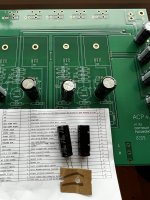
ACP: CAP-TASTIC EDITION
This build has been a bit of a slow burn.
I built Papa's ACP+ at it's Burning Amp introduction. I've used the ACP+ as a headphone amp and as a preamp. It still gets a regular rotation and brings back a fond memory every time it plays.
When Cody T introduced his layout of the ACP+ (post #1901 with gerbers / BOM post #1913, this thread), I had to try it. The Cap Tastic Edition seemed like all of Papa's original design with some added tweaks to push it more into the preamp world. Perfect for a guy who doesn't go to the office or listen to headphones much any more.
I ordered the gerbers and built the boards. Life got in way and everything got put in a box on a shelf. I'd check this thread now and then but no one ever fessed up to following Papa's and Cody T's path. Which is a shame. More of us should try this version of the ACP+.
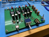
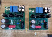
I've finally got my boards up and running and they sound great. I'm impressed how good it all sounds in front my Vfet amp. It's an easy build and you can still use a +24v SMPS to power both channels. A small box, some RCA jacks, an Alps pot and an SMPS filter are all you need.
I've got it all running on my sloppy preamp test rig. I'll post some better photos once I get it into a permanent home. Until then, I've added a pic of the boards as proof I'm not just making this stuff up.
Disclaimers/Notes-
As always, I blame Pa and Cody T, too!
This build has been a bit of a slow burn.
I built Papa's ACP+ at it's Burning Amp introduction. I've used the ACP+ as a headphone amp and as a preamp. It still gets a regular rotation and brings back a fond memory every time it plays.
When Cody T introduced his layout of the ACP+ (post #1901 with gerbers / BOM post #1913, this thread), I had to try it. The Cap Tastic Edition seemed like all of Papa's original design with some added tweaks to push it more into the preamp world. Perfect for a guy who doesn't go to the office or listen to headphones much any more.
I ordered the gerbers and built the boards. Life got in way and everything got put in a box on a shelf. I'd check this thread now and then but no one ever fessed up to following Papa's and Cody T's path. Which is a shame. More of us should try this version of the ACP+.
I've finally got my boards up and running and they sound great. I'm impressed how good it all sounds in front my Vfet amp. It's an easy build and you can still use a +24v SMPS to power both channels. A small box, some RCA jacks, an Alps pot and an SMPS filter are all you need.
I've got it all running on my sloppy preamp test rig. I'll post some better photos once I get it into a permanent home. Until then, I've added a pic of the boards as proof I'm not just making this stuff up.
Disclaimers/Notes-
- I tried to use nice components and I did have a spare pair of 2SK2013 handy. I know, I know.....
- I used 2SJ74's and 2SK170 for the input buffer.
- I found the LED pins +- on the boards were backwards.
- I connected my signal out from the Alps pot to W and the signal out ground to CW. ( I have no idea what CCW, W and CW mean). I'm sure someone will share their wisdom.
- The 1K pot adjusts the voltage into Q7 as measured across R15. Set one probe to ground and the other (+) to the side of R15 closest to the center of the board. Adjust the pot to see half the supply voltage. 24V in, so set to 12v. Easy, right?
As always, I blame Pa and Cody T, too!
Attachments
- Home
- Amplifiers
- Pass Labs
- Amp Camp Pre+Headphone Amp - ACP+