I'm a newbie here but wondering if anyone can share insight on the availability of the kits. Looks like the parts kit is out of stock. Do they generally come back in stock pretty quick? Thanks
I'm a newbie here but wondering if anyone can share insight on the availability of the kits. Looks like the parts kit is out of stock. Do they generally come back in stock pretty quick? Thanks
I don‘t know about how long you would have to wait for kits from the shop, but I have 2 kits. Wanted to do some experiments, but I‘m „in the process of changing my mind“.
PM me if you’re interested.
David
I'm a newbie here but wondering if anyone can share insight on the availability of the kits. Looks like the parts kit is out of stock. Do they generally come back in stock pretty quick? Thanks
There are currently out of stock, and looks like 3 months before we will have new stock. We're planning on doing some "quality of life" updates, such as silkscreening the rear panel to make it easier to understand the various monoblock connection options, so stay tuned.
There are currently out of stock, and looks like 3 months before we will have new stock. We're planning on doing some "quality of life" updates, such as silkscreening the rear panel to make it easier to understand the various monoblock connection options, so stay tuned.
The parts kit is out of stock, but the chassis and power supply appear to be available. Any chance the Parts Kit is back in stock sooner than 3 months? I only ask because the “quality of life” bits you referenced don’t seem like they are related to anything in the “parts kit”. I ask because I am happy to purchase the three items separate (chassis, power supply and parts kit) if available sooner than 3 months.
Any chance the Parts Kit is back in stock sooner than 3 months?
Very unlikely. We're running a bit late on the re-supply of this kit as there was an interview with Nelson a few months back which caused quite a few sales right as we were getting to the end of stock. This caught us and our supply chain off guard. All the store's kits are put together by DIYers such as yourself on their proverbial kitchen benches. Often they have one or two parts which are problematic to obtain, or have long lead times. And as the saying goes, sometimes "life just gets in the way".
If you do really want to make the ACA in the meantime, you could buy the ACA PCBs and do-it-yourself. Nelson's article states the parts can cost as little as $15 if you want to go surplus shop hunting for bargains (and can find some 2SK170s/LSK170s, and have your own stash of common connectors, switches, insulators, LEDs, wire, jacks, standoffs, nuts and bolts etc).
Hi folks,
I built the ACA 1.6 this past summer. I was happy with the way it sounded and the volume level it produced w/ my ~90dB sensitivity speakers. All voltages looked good (double-checked again today), etc. No issues.
A few months ago I picked up my first oscilloscope and an 8 ohm non-inductive dummy load resistor and decided to measure the output level of the ACA. I've used the same setup to measure other amps without any issues.
But the measurements I'm getting from the ACA don't make any sense, and the 1KHz tone gets distorted at very low levels.
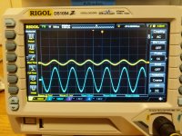
In the following photos I've got the dummy load on CH1 (yellow trace) and the output of my volume-adjustable DAC on CH2 (blue trace). I'm confused by what I'm seeing.
Any idea what is going on? Music does start to sound a little funky at higher volume levels.
I'm a total newbie w/ the scope so maybe I'm missing something here.
First image is w/ volume very low - here you can see the scale is set the same for both channels on the scope (100mV)
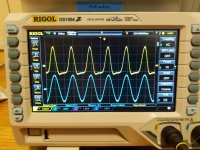
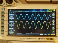
Second two images show the point at which the sine wave starts to distort and then the DAC output at its maximum level. Notice that the scale is set 10x higher on CH2 (DAC output) than CH1 (dummy load attached to ACA). Both probes are set to 1x both on the probe and on the scope. (Not sure why one of them is showing upside-down...)
I built the ACA 1.6 this past summer. I was happy with the way it sounded and the volume level it produced w/ my ~90dB sensitivity speakers. All voltages looked good (double-checked again today), etc. No issues.
A few months ago I picked up my first oscilloscope and an 8 ohm non-inductive dummy load resistor and decided to measure the output level of the ACA. I've used the same setup to measure other amps without any issues.
But the measurements I'm getting from the ACA don't make any sense, and the 1KHz tone gets distorted at very low levels.
In the following photos I've got the dummy load on CH1 (yellow trace) and the output of my volume-adjustable DAC on CH2 (blue trace). I'm confused by what I'm seeing.
Any idea what is going on? Music does start to sound a little funky at higher volume levels.
I'm a total newbie w/ the scope so maybe I'm missing something here.
First image is w/ volume very low - here you can see the scale is set the same for both channels on the scope (100mV)
Second two images show the point at which the sine wave starts to distort and then the DAC output at its maximum level. Notice that the scale is set 10x higher on CH2 (DAC output) than CH1 (dummy load attached to ACA). Both probes are set to 1x both on the probe and on the scope. (Not sure why one of them is showing upside-down...)
Attachments
Be careful, the black output ls connector is signal, red is gnd. If you connect the gnd of the probe to the black connector you short the output, if you connect the second probe gnd clip on the input at the gnd of the rca connector.
Welp, thank you for the quick help. That solved it.
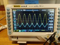
Here's the scope with the probe leads reversed, same test signal, etc.
Seems w/ a 1V signal in I'm getting a max of about 1.2W out. I see what Nelson is saying all the time about "1W is louder than you think." 🙂
Here's the scope with the probe leads reversed, same test signal, etc.
Seems w/ a 1V signal in I'm getting a max of about 1.2W out. I see what Nelson is saying all the time about "1W is louder than you think." 🙂
Attachments
JFET Mishap
My high school son and I were congratulating each other on our pretty solder joints...then one of us soldered Q4 LK170 in “backward”—drain and gate reversed. After an ugly fix, I’m worried we fried the jfet.
Is there a way with a multimeter to see if the in situ, correctly oriented, but abused jfet Q4 is still alive? I would prefer to pause, get a replacement part, rather than finish the build to find one dead channel.
Please help as my kid is dying to hear Slipknot and The Offspring through a Pass circuit. On second thought...
Measure RDS. Its resistance between drain and source pins with power OFF. Circa 30 Ohm for a medium IDSS K170 is a healthy indication. Certainly not a short or an open indication or some kΩ for any IDSS. Compare with the K170 on the other channel.
No need to remove the part from the board in most cases for measuring that parameter.
I did EXACTLY the same thing! Of course, not with a simple cap or replaceable part, with the unobtanium (then, now just pricey! 😛) part.My high school son and I were congratulating each other on our pretty solder joints...then one of us soldered Q4 LK170 in “backward”—drain and gate reversed. After an ugly fix, I’m worried we fried the jfet.
Is there a way with a multimeter to see if the in situ, correctly oriented, but abused jfet Q4 is still alive? I would prefer to pause, get a replacement part, rather than finish the build to find one dead channel.
Please help as my kid is dying to hear Slipknot and The Offspring through a Pass circuit. On second thought...
Luckily, it was perfect, no damage done even if the legs ended up crooked and the poor guy was heated severely during de-solerding.
I hope yours is as resilient as mine was!
Rafa.
Salas and Rafa
Thank you for your helpful and encouraging replies. Salas, resistance measurement between drain and source in abused jfet approximately the same as jfet on other board: ~35 ohms. Thank you for your help—feel more confident we’ll have a working amp soon.
Thank you for your helpful and encouraging replies. Salas, resistance measurement between drain and source in abused jfet approximately the same as jfet on other board: ~35 ohms. Thank you for your help—feel more confident we’ll have a working amp soon.
I'm doing a 4-way active build with Two (2 pcs) Firstwatt M2's. One on midbass (2 x 15") and one on midrange (2 x 8"). Sub (2 x 21") will be powered by a Crown XLS. As tweeter I will use Beyma TPL-150B.
Would a Amp Camp Amp be suitable for the TPL's? Total system sensitivity will be around 100dB so I guess the power of the ACA is enough.
The TPL also seems to be an easy load, see pic.
😕

Would a Amp Camp Amp be suitable for the TPL's? Total system sensitivity will be around 100dB so I guess the power of the ACA is enough.
The TPL also seems to be an easy load, see pic.
😕
Help! Suddenly no sound out of one Channel. All voltage Checks are OK. Items is also warming up. Any idea?
If you swap the left and right inputs round does the fault follow the input?
If you swap the left and right speakers round does the fault follow the speakers?
If no, then most likely to be a bad connection / solder joint. Look at the input and output connections.
If you swap the left and right speakers round does the fault follow the speakers?
If no, then most likely to be a bad connection / solder joint. Look at the input and output connections.
How much experience do you have soldering? I wasn't flowing solder into the joints quite long enough on my first ACA and also had one channel go quiet after less than a week of use. Alan4411's suggestion sounds good, but really look at your solder joints and think about at least reheating them so solder really gets down into the joint.
Troubleshooting question:
Does anyone have some sort of digital fart sound from the amp when first turning it on? It lasts about 2 seconds then goes away. Other than that, the amp sounds clean on both channels.
Thanks,
Billy
Does anyone have some sort of digital fart sound from the amp when first turning it on? It lasts about 2 seconds then goes away. Other than that, the amp sounds clean on both channels.
Thanks,
Billy
Capacitor
It is the capacitor charging. This is normal and happens everytime the power switch is turned on.😀
It is the capacitor charging. This is normal and happens everytime the power switch is turned on.😀
It is the capacitor charging. This is normal and happens everytime the power switch is turned on.😀
Thanks!
I’m running a Bluesound Node 2i, amp camp 1.6 in stereo on Klipsch RP-600M speakers. Treble is a little crispy but everything sounds clear through Tidal streaming. I have been running it full range and when wife permits, I add a SVS SB-3000.
It took me about 3 months to decide on a set of high efficiency speakers for this. This weekend I’m hoping to do the GR Research Klipsch speaker upgrade to the box and crossover.
I need to finish wiring up my second amp to make monoblocks.
Billy
- Home
- The diyAudio Store
- Amp Camp Amp Kit 1.6/1.8