Yep,
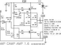
Look at the circuit diagram. The +ve out is the same track as the GND. The -ve out connects to the output cap C1.
The printing on the boards matches the -OUT and +OUT of the diagram.
Look at the circuit diagram. The +ve out is the same track as the GND. The -ve out connects to the output cap C1.
The printing on the boards matches the -OUT and +OUT of the diagram.
Attachments
Last edited:
Success! Thanks much!
What temperatures are you seeing close to the junction between transistors and heat sinks? I think most people are too conservative regarding temperature.
I understand ACA is draining ~3 amps from the irfp240s and if I’m correct they are rated to run at 140C or 284F at the case at 3 amps. Of course it would make the heatsink a bit dangerous, but wouldn’t affect transistor life.
After it warmed up for 10 minutes, I put my hands on it for 10 seconds and it was pretty uncomfortable.
After it warmed up for 10 minutes, I put my hands on it for 10 seconds and it was pretty uncomfortable.
I found a meat thermometer works good too. At ten seconds you’re probably around 60C -140F. If this is at the transistor itself I would say you’re running at what most people do in the forum.
Keep in mind that although most of the heatsink will be at the same temperature, the transistor case is noticeable hotter since the interface with the heatsink has poor conductivity even with paste and mica which are quite a bit better than silicone pads. And then the transistor die itself would be even hotter because it’s conductivity to the base plate is also not great.
150C is the maximum temperature of the die. If you look in the data sheet you’ll see a chart of the maximum casing allowable temperature per current being drained. You see that the hotter the die is, the cooler the casing must be kept at. That’s because heat takes time to transfer and the die is hotter than the case.
But 10 seconds is actually cool enough to not worry about. So that’s good. 🙂
If you want it cooler place the amp elevated a little so there’s 2” below the heatsinks. Having the space below greatly helps the chimney effect.
If you want it cooler place the amp elevated a little so there’s 2” below the heatsinks. Having the space below greatly helps the chimney effect.
Very low volume
I’ve built a few of these ACA’s and have had no problems. With this last one I wasn’t patient for the kit, and procured every part separately myself. I did my best, but honestly I hardly know what I’m buying. I think the small resistors are fine, but I’m concerned about the power resistors, and the capacitors. I just matched the specs and bought the more expensive of the options. Additionally, I got creative with my choice of wires in a fun attempt for consistency of input and output wires. Maybe that was a mistake. Ultimately, there is sound, but very low volume. I followed the troubleshooting pics in the build guide and all check good in the powered up mode. However in the non powered mode the numbers don’t match well. They kinda bounce around. Any thoughts?
I’ve built a few of these ACA’s and have had no problems. With this last one I wasn’t patient for the kit, and procured every part separately myself. I did my best, but honestly I hardly know what I’m buying. I think the small resistors are fine, but I’m concerned about the power resistors, and the capacitors. I just matched the specs and bought the more expensive of the options. Additionally, I got creative with my choice of wires in a fun attempt for consistency of input and output wires. Maybe that was a mistake. Ultimately, there is sound, but very low volume. I followed the troubleshooting pics in the build guide and all check good in the powered up mode. However in the non powered mode the numbers don’t match well. They kinda bounce around. Any thoughts?
Attachments
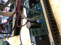
Resistors and caps 'look' ok. As long as you chose the same value and voltage rating for the caps they should be fine.
Not sure I understand the ''kinda bounce around'' in the above statement.
Did you put 'insulators' under Q1 and Q2? Do both Q1 and Q2 get hot? Can you adjust the 'bias' to 12 volts?
If yes to the above - Have you checked the resistance from the Red to Black output terminals? It should be about 1K ohms. If it is very low, you have the outputs shorted. Make sure their metal parts do not /cannot touch the chassis.
Remember, if you are following the build guide, the Black terminal is Not connected to the GND / 0volt. The + OUT from the board is the GND / 0 volt line and connects to the Red terminal. (Have a look at the circuit diagram in post #661.)
Alan
... Ultimately, there is sound, but very low volume. I followed the troubleshooting pics in the build guide and all check good in the powered up mode. However in the non powered mode the numbers don’t match well. They kinda bounce around. Any thoughts?
Not sure I understand the ''kinda bounce around'' in the above statement.
Did you put 'insulators' under Q1 and Q2? Do both Q1 and Q2 get hot? Can you adjust the 'bias' to 12 volts?
If yes to the above - Have you checked the resistance from the Red to Black output terminals? It should be about 1K ohms. If it is very low, you have the outputs shorted. Make sure their metal parts do not /cannot touch the chassis.
Remember, if you are following the build guide, the Black terminal is Not connected to the GND / 0volt. The + OUT from the board is the GND / 0 volt line and connects to the Red terminal. (Have a look at the circuit diagram in post #661.)
Alan
Also check for cracked/cold solder joints and reflow them. Its hard to tell from your picture, but that is something I've had happen a few times when building these with my kids (or my first one). In particular, the pins on the MOSFETs are thicker and need a little more heat in my experience, and that is a common place where I've found the obvious non-shiny finish to the joints. A simple reflow and you're in business.
--Tom
--Tom
Last edited by a moderator:
Just to stem any confusion - because I had to think twice about the statement below about the +OUT connected to the red (positive) speaker terminal) as I'd forgotten the circuit inverts, so you do use the actual negative/return as the positive speaker output (correctly marked +OUT on the board), and the actual positive as -OUT (again correctly marked on the board). The boards are marked and consistent with the build guide here:
ACA illustrated build guide
Take a look and make sure you have wired things this way.
Keep in mind that wiring the output either way shouldn't have anything to do with your drop out issue you mention (unless there is some cold solder joint/etc... on those points); in this case you will just have inverted output if wired backwards but there should be no intermittent dropping of the output signal.
--Tom
Resistors and caps 'look' ok. As long as you chose the same value and voltage rating for the caps they should be fine.
Not sure I understand the ''kinda bounce around'' in the above statement.
Did you put 'insulators' under Q1 and Q2? Do both Q1 and Q2 get hot? Can you adjust the 'bias' to 12 volts?
If yes to the above - Have you checked the resistance from the Red to Black output terminals? It should be about 1K ohms. If it is very low, you have the outputs shorted. Make sure their metal parts do not /cannot touch the chassis.
Remember, if you are following the build guide, the Black terminal is Not connected to the GND / 0volt. The + OUT from the board is the GND / 0 volt line and connects to the Red terminal. (Have a look at the circuit diagram in post #661.)
Alan
Just to stem any confusion - because I had to think twice about the statement below about the +OUT connected to the red (positive) speaker terminal) as I'd forgotten the circuit inverts, so you do use the actual negative/return as the positive speaker output (correctly marked +OUT on the board), and the actual positive as -OUT (again correctly marked on the board). The boards are marked and consistent with the build guide here:
.............
Keep in mind that wiring the output either way shouldn't have anything to do with your drop out issue you mention (unless there is some cold solder joint/etc... on those points); in this case you will just have inverted output if wired backwards but there should be no intermittent dropping of the output signal.
--Tom
Hi Tom, you are correct that the amp inverts, hence the red speaker terminal going to 0 volts / GND. That causes some confusion...
But your statement, ''that wiring the output either way shouldn't have anything to do with your drop out issue you mention'', is only true for the original 1.0 builds.
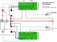
The OP has built a couple of ACAs before and I suspect he is using the current Build Guide (1.6 here Amp Camp Amp V1.6 Build Guide - diyAudio Guides) not the one you referenced. The 0 volt and speaker connection are different from 1.0 builds to 1.6 builds... I've attached a later layout to show the problem.
If the OP has connected the -ve OUT from the board to the 0 volt / GND input connection, then the output is shorted. (On the boards themselves the GND track connects to the +ve OUT terminal.) The test in my first reply about measuring the 1k resistance between the speaker terminals will soon tell him if that is a problem or not. There are many possible reasons of course, poor solder joints and possible fake parts etc. But with the limited information - one step at a time.
Alan
Attachments
Last edited:
Resistors and caps 'look' ok. As long as you chose the same value and voltage rating for the caps they should be fine.
Not sure I understand the ''kinda bounce around'' in the above statement.
Did you put 'insulators' under Q1 and Q2? Do both Q1 and Q2 get hot? Can you adjust the 'bias' to 12 volts?
If yes to the above - Have you checked the resistance from the Red to Black output terminals? It should be about 1K ohms. If it is very low, you have the outputs shorted. Make sure their metal parts do not /cannot touch the chassis.
Remember, if you are following the build guide, the Black terminal is Not connected to the GND / 0volt. The + OUT from the board is the GND / 0 volt line and connects to the Red terminal. (Have a look at the circuit diagram in post #661.)
Alan
I did put insulators under Q1 and Q2, however they are small and thin compared to the Keratherm. Q1 and Q2 get hot and I was able to set at 12V. The resistance on the black and red speaker posts is .4 ohms. So very low. (On another build it did run up to 1k ohms, so I know I’m checking correctly, but that was a previous version of the board). I checked the solder and ensured nothing was touching the chasis. Visually it looks fine. I followed the build guide and ran the + as marked on the board to the red post, and the - to the black post. I’m assuming that’s correct, but am I to reverse those? If so, on the pcb, or on the speaker posts?
Okay,
It does not matter which version of the board you have, the resistance between the speaker sockets has to be about 1K. Less than an ohm is a short somewhere.
Start by taking both 'speaker wires' off one of the boards and measure the resistance from +OUT to -OUT on the board. That should be about 1K. If it is, then the short is in the wiring or sockets. If it is the 0.4 ohms figure, the short is something on the board.
Check the negative power input connector, outer ring, does go to the Red speaker sockets?
Then, need to see more pictures now of how you have wired the speaker connections etc.
Last edited:
It’s the speaker sockets. Looks like they need to be isolated from the metal chasis. I nutted on the back with the metal lock washer and thus the whole back plate became the short. Thanks so much!!! Generous of you, and others on this site, to be so helpful.
Glad you have it sorted.
Yes all 4 need to be insulated from the chassis.
And glad to help.
Enjoy, Alan
Yes all 4 need to be insulated from the chassis.
And glad to help.
Enjoy, Alan
Ah nice catch. I failed to understand that he is building a latest edition.
I am actually currently working on an original 1.0 build right now, which explains things. 🙂
--Tom
I am actually currently working on an original 1.0 build right now, which explains things. 🙂
--Tom
Hi Tom, you are correct that the amp inverts, hence the red speaker terminal going to 0 volts / GND. That causes some confusion...
But your statement, ''that wiring the output either way shouldn't have anything to do with your drop out issue you mention'', is only true for the original 1.0 builds.
The OP has built a couple of ACAs before and I suspect he is using the current Build Guide (1.6 here Amp Camp Amp V1.6 Build Guide - diyAudio Guides) not the one you referenced. The 0 volt and speaker connection are different from 1.0 builds to 1.6 builds... I've attached a later layout to show the problem.
If the OP has connected the -ve OUT from the board to the 0 volt / GND input connection, then the output is shorted. (On the boards themselves the GND track connects to the +ve OUT terminal.) The test in my first reply about measuring the 1k resistance between the speaker terminals will soon tell him if that is a problem or not. There are many possible reasons of course, poor solder joints and possible fake parts etc. But with the limited information - one step at a time.
Alan
It’s the speaker sockets. Looks like they need to be isolated from the metal chasis. I nutted on the back with the metal lock washer and thus the whole back plate became the short. Thanks so much!!! Generous of you, and others on this site, to be so helpful.
Something to add to your build list: When installing any chassis-mounted connector, check continuity between it and the chassis, and then as a final pre-flight/plug-in test.
Also make sure you really tighten the connectors down so that they don't accidentally rotate in the sockets and come loose, or slide the post so it touches the chassis.
--Tom
- Home
- The diyAudio Store
- Amp Camp Amp Kit 1.6/1.8