Another approach would be to open up the supplies and see if you could increase heat sinking on the active components that may be heating up. This will not help if the problem is with the magnetics heating up. It just seems like over kill to use 2 fans, even quiet ones, when only a few watts of heat are causing the issue.
I have experimented with the cheap +- 500w SMPS supplies from EBAy. The transistors overheat quickly if they are asked to supply a continuous load. In that case I added larger heatsinks and solved that issue. However, that type of supply is very crude and is not regulated. It produces huge amounts of rf interference and a lot of shielding and filtering would be needed to use one in a high end amplifier.
I feel high quality SMPS are a good alternative and worth investing some time to trailer to the requirements of your build. One issue that keeps coming up for me in class A builds is transformer buzz. No worries about that with the SMPS. And no need for 500$ potted toroids to prevent the buzz.
Your setup looks real good Andy! Your AN should run cool as a cucumber now 😀
Yes, I'm thinking it should - now I've got the fans mounted the way you suggested, V! 🙂
Just double check if the fans will operate without a PWM controller.
Good point - I have emailed Noctua Support!
Andy
Thanks X and Hugh for great amp. I am still in early stages, heatsinks only arrived today. I built boards about a week ago, and was waiting for delivery of heatsinks. Just tested a birdsnest with variac, works from the start. I am running it with test speakers though caps first to break it in. I will put it together in few days. It shows great promise. Cheers! Stay safe.
Attachments

I checked that option also but the original fan is only 15mm deep. The case cannot accommodate 25mm thick internal fans.
Jacques
Maybe use the 14mm thick Noctua fans that I am using - Noctua NF-A9x14 PWM 92mm Premium Fan?
Andy
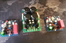
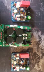
Nice fast work there Adason! Another Alpha Nirvana is born!
Are those motor run caps in those large rectangular blocks?
Are those motor run caps in those large rectangular blocks?
Nice work Jacques and Adason!!
Two Alpha Nirvana’s born this week and soon Andy will be flipping the switch 😀
Looking forward to seeing them all buttoned up.
Enjoy
Two Alpha Nirvana’s born this week and soon Andy will be flipping the switch 😀
Looking forward to seeing them all buttoned up.
Enjoy
Hi Andy,
Those thin Noctua’s are slick, very low profile. Lookin’ good!
Yes, they were a great suggestion, V - thank you! 🙂
But do you happen to know which male base matches the 4-pin female connectors on the end of the fan's cable?
Would this Molex connector match it?:
https://au.rs-online.com/web/p/pcb-headers/6795596/
Why I ask is that I will be building a little board to hold the voltage step-down resistors:
* on the input end of this board will be wires which come from the power spades on the SLB,
* on the output end will be a male connector to fit the Noctua socket
* and, I'll use a pair of Phoenix connectors to hold the resistor, for each fan, so I can easily change the value, to give the correct voltage for the fan.
Andy
Andy,
I don’t know the Molex part number of the matching connector for the fan lead. But, since you’re not using a PWM controller you’re only going to use two of the four wires, 12V and Gnd. First I would confirm that that fan is capable to work in that configuration, if it is, just cut the connector off and make your own 2-pin molex KK connector. (Same 2 conductor molex connectors used on the AN board)
I don’t know the Molex part number of the matching connector for the fan lead. But, since you’re not using a PWM controller you’re only going to use two of the four wires, 12V and Gnd. First I would confirm that that fan is capable to work in that configuration, if it is, just cut the connector off and make your own 2-pin molex KK connector. (Same 2 conductor molex connectors used on the AN board)
Andy,
I don’t know the Molex part number of the matching connector for the fan lead. But, since you’re not using a PWM controller you’re only going to use two of the four wires, 12V and Gnd. First I would confirm that that fan is capable to work in that configuration, if it is, just cut the connector off and make your own 2-pin molex KK connector. (Same 2 conductor molex connectors used on the AN board)
Just found I have an easier solution to hand, V !! 🙂
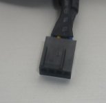
The actual socket on the end of the fan cable is shown in the 1st attached pic.
This matches the male plugs on the PWM controller - see 2nd attached pic. This is obviously a standard plug used by computer mfrs.
I searched for both Molex and Worth 4-pin, in-line male connectors and they all have the vertical 'locking piece' going the full width of the pins - so they don't mate with the Noctua socket. 🙁
However, the vertical 'locking piece' on a 3-pin Molex connector does mate with the Noctua socket - and the 4th pin just hangs off the end!
I have some 3-pin Molex in-line male connectors (I bought them to match with the 120mm (non-Noctua) fans I bought initially) - so will use these ... and keep the 4-pin sockets on the fan cables. 🙂
This will enable me to use the supplied "NA-RC7 Low-Noise adapter cable" in winter, and - if the heating doesn't work as well as I'm expecting it to - remove this cable for summer operation, to get the full 2200rpm. 🙂
Andy
Attachments
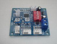
Andy, my 4 pin Noctua PWM connector fits that motor control board perfectly. It senses fan speed which is important as it is actively controlled. I am not sure why yours does not fit?
Mine looks just like this and if you look carefully you see there is a polarized little channel on one end and that mates perfectly with the 4 pin connectors in the PWM board.

Andy, since you have the 4pin PWM fan and PWM fan controller. Why don’t you just use it as is like it was designed? That controller allows you to vary the speed with those pots and dip switches. It’s very easy and convenient. I mean they took a 6month project of a PWM controller with temp sensor and audible alert with set points for fan speed up and made it for $5. You are tryig to defeat a marvel of engineering - why?
At least try it as intended and tell me what’s wrong with it. Then maybe go off and do it differently.
Mine looks just like this and if you look carefully you see there is a polarized little channel on one end and that mates perfectly with the 4 pin connectors in the PWM board.
Andy, since you have the 4pin PWM fan and PWM fan controller. Why don’t you just use it as is like it was designed? That controller allows you to vary the speed with those pots and dip switches. It’s very easy and convenient. I mean they took a 6month project of a PWM controller with temp sensor and audible alert with set points for fan speed up and made it for $5. You are tryig to defeat a marvel of engineering - why?
At least try it as intended and tell me what’s wrong with it. Then maybe go off and do it differently.
Attachments

Last edited:
Andy, my 4 pin Noctua PWM connector fits that motor control board perfectly. It senses fan speed which is important as it is actively controlled. I am not sure why yours does not fit?
Mine looks just like this and if you look carefully you see there is a polarized little channel on one end and that mates perfectly with the 4 pin connectors in the PWM board.
Yes, X - the 4 pin Noctua PWM connector fits the connectors on the PWM motor control board. 🙂
Andy, since you have the 4pin PWM fan and PWM fan controller. Why don’t you just use it as is like it was designed? That controller allows you to vary the speed with those pots and dip switches. It’s very easy and convenient. I mean they took a 6month project of a PWM controller with temp sensor and audible alert with set points for fan speed up and made it for $5. You are trying to defeat a marvel of engineering - why?
At least try it as intended and tell me what’s wrong with it. Then maybe go off and do it differently.
I just wanted to see if I could get away without using PWM ... to simplify matters! 🙂
Andy
I just wanted to see if I could get away without using PWM ... to simplify matters! 🙂Andy
Becareful when setting using only resistor for throttling the pc fan, if set too near threshold, it may still spins but will also stop when you least expected.
Happens to me many time.
Be careful when setting using only resistor for throttling the pc fan, if set too near threshold, it may still spins but will also stop when you least expected.
Happens to me many time.
Yes, understood, m. 🙂
I'm using a res to reduce the 20-22v +ve DC output (have to wait and see what it turns out to be, when the amp is up and running) on my SLBs down to 12v for the fan - not 'throttling' the fan by lowering the voltage further.
Andy
I thought I would innovate using SMPS for my AN build. So I did.
Great sound, especially bass. No hum, no hiss between tracks. Positive WAF.
But after some listening time, the MeanWell SMPS fans kicked in: a different story. Loud!
My preliminary bench tests were not long enough to start the fans and I thought they would never turn on….
Well, it’s time to start building a proper linear PSU!
Jacques
I just connected my two 800w 48v SMPS’s together in series. I verified that outputs are electrically isolated from chassis and earth ground. I put 8D-20 NTC between earth ground and common 0v point on both. Looks like it works fine. I have it boosted to +/-50v AN’s supplies say they are rated for 16A (with fan).
These are very quiet supplies (I do not see any noise in audible range on FFT and noise floor is -127dB, not even a hint of 60Hz bump).
I might make an Alpha Big Boy Turbo at +/-50v 3A bias. 😀
- Home
- Amplifiers
- Solid State
- Alpha Nirvana 39w 8ohm Class A Amp