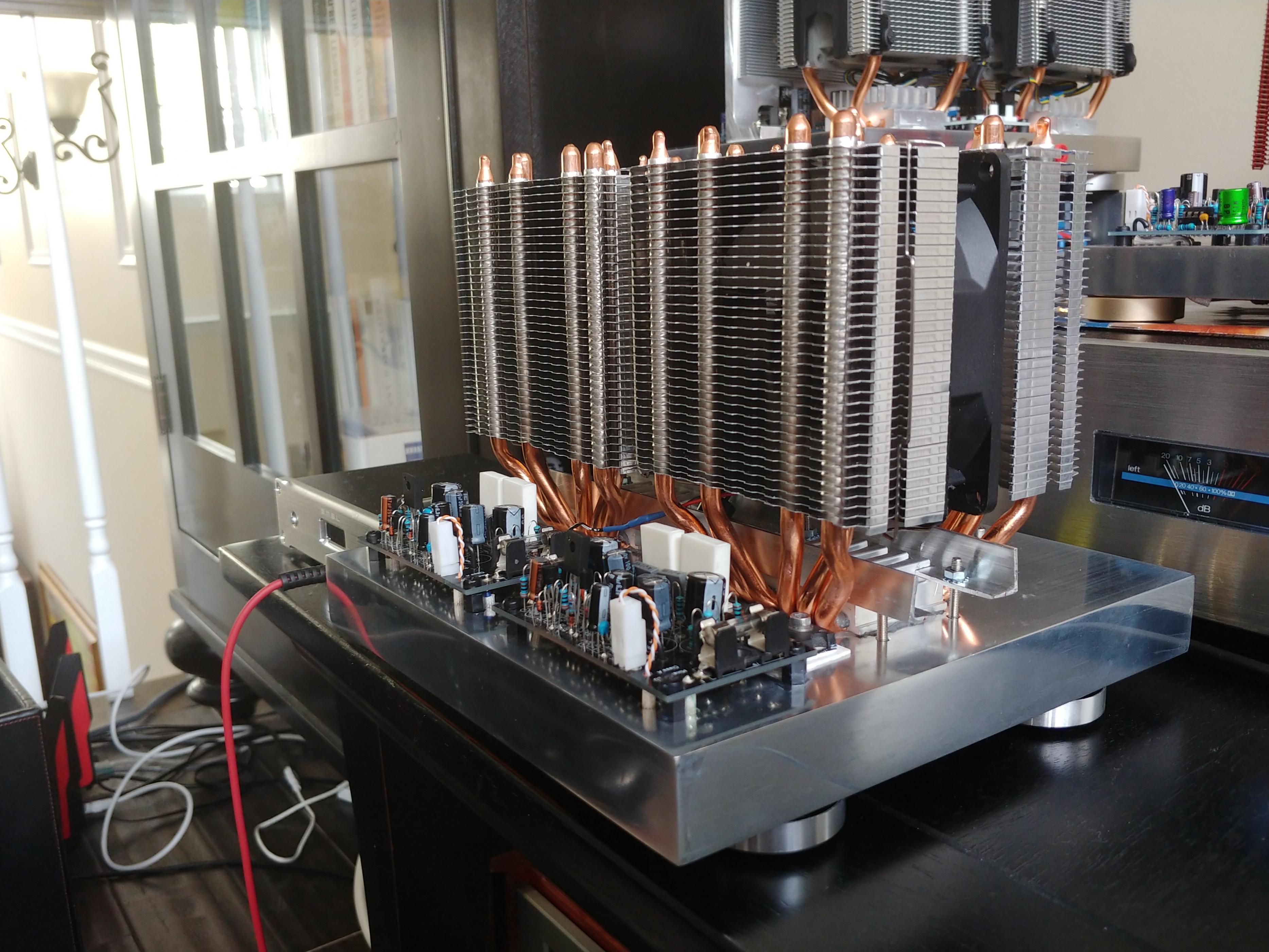
Here is a latest trio of actively cooled amps, right-bottom is AN.
It has the beefiest fans (6 heat pipes), and thickest chassis...
The other two, with smaller fans, rarely run hotter than human body,
with fans barely moving..
I like it...
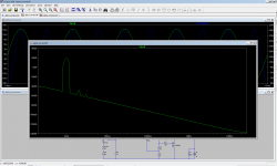
Just completed AN build.
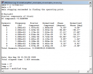
Tested, scoped, everything looks good.
Now time for thermal tests 🙂
Need to plug it in, and watch the temperature for a few hours, to see if these 2 heatsinks and fans are enough.
So far, after 10 min running, output transistors are running at 60 degrees C
(21V rails, will test 27V as a next step)..
PSU is external one - the box in the back, with VU meters. It's +/-80V (800W),
with speaker protection and VU meters.
I have auto-transforer in front of it, so I can adjust voltage as needed.
AN chassis is made from Alu slab, 8x8, 1 inch thick.
2 little boards behind the fans - voltage regulator to drop +rail to 12V, and fan controller.
PCBs are obviously different - smaller then originals, with power FETs soldered directly to the boards.
Thermistor sensor from the fan controller, is glued with thermal glue to one of the output transistors, but I guess
it doesn't matter - I expect these fans to run constantly...
More pics at http://www.slowbears.com/flickr/AlphaNirvana/
Very cool! 🙂
Andy
Yes, I can.
Also, 60C was observed BEFORE I glued thermistor to the output fet.
First, it was connected to the CPU heatsink.
Now, when it's directly sensing temperature of the fet, fans will kick in sooner, and at higher speed.
Fets are bolted VERY close to CPU heatsinks.
60C is not too bad, I'd be happy if it stays at 60C.
I built and tested this kind of cooling with other amps, but not A class, so we will see...
60 is about the same as me... in fact, I'm not getting freaked out unless I see 70C. I'm new, but I can leave me finger on the chip as long as I want without having to remove it, so I'm not so sure I can trust the temp readings. If I can put my finger on the chip and not have to remove it, or get burned, I'll listen and not trip.
JT
How many degrees F above ambient are your CPU coolers getting to, V?
Andy
@Andy,
I’m not using cpu coolers for my Alpha Nirvana. I went the conventional aluminum HS route with a Modushop 5U 400mm chassis.
@mineK123,
Cool looking build! Just keep an eye on the Mosfet temps 😉
Hi mineK123,
I love your slab chassis! That’s got to be the best looking minimalist chassis I have seen. Way more interesting than a box with fins. The 1in slab appears to be machined out on the bottom side because I see RCA jacks etc feeding through the back edge like a panel. Is it hollowed out on the underside or just strategically milled where necessary?
It occurs to me that you could have milled or drilled in channels for water cooling in the slabs and clamped your MOSFETs the other way. Then have two tubes go to a separate water cooling radiator unit. Although the fins and fans look way cooler.
Which brand/model is that copper finned one? Never seen that before.
Congrats! Beautiful work.
Hi Minek123,
Now you have run your AN 40 for a few hours, maybe days, could you describe the sound quality? Are you happy with it?
Very professionally done, congratulations for a great job. Excellent two fans for four towers, economical cooling system.
HD
Now you have run your AN 40 for a few hours, maybe days, could you describe the sound quality? Are you happy with it?
Very professionally done, congratulations for a great job. Excellent two fans for four towers, economical cooling system.
HD
Last edited:
Just completed AN build.
Tested, scoped, everything looks good.
Now time for thermal tests 🙂
Need to plug it in, and watch the temperature for a few hours, to see if these 2 heatsinks and fans are enough.
So far, after 10 min running, output transistors are running at 60 degrees C
(21V rails, will test 27V as a next step)..
PSU is external one - the box in the back, with VU meters. It's +/-80V (800W),
with speaker protection and VU meters.
I have auto-transforer in front of it, so I can adjust voltage as needed.
AN chassis is made from Alu slab, 8x8, 1 inch thick.
2 little boards behind the fans - voltage regulator to drop +rail to 12V, and fan controller.
PCBs are obviously different - smaller then originals, with power FETs soldered directly to the boards.
Thermistor sensor from the fan controller, is glued with thermal glue to one of the output transistors, but I guess
it doesn't matter - I expect these fans to run constantly...
More pics at http://www.slowbears.com/flickr/AlphaNirvana/
wow, that's a beauty!
Here is a latest trio of actively cooled amps, right-bottom is AN.
It has the beefiest fans (6 heat pipes), and thickest chassis...
The other two, with smaller fans, rarely run hotter than human body,
with fans barely moving..
Congratulations Minek for your ....sexy build 🙂🙂🙂!
Jacques
Minek!
Art deco build, love it! Awesome! Please give us your subjective impressions of the amplifier once you get a chance.
Best,
Anand.
Art deco build, love it! Awesome! Please give us your subjective impressions of the amplifier once you get a chance.
Best,
Anand.

The 1in slab appears to be machined out on the bottom side because I see RCA jacks etc feeding through the back edge like a panel. Is it hollowed out on the underside or just strategically milled where necessary?
Yeah, all the cables and connectors had to go somewhere, to keep surface
uncluttered.
The 1st thing was for PSU to be 'outsourced' and connected
by cable. I wanted to do it for different reason - too many amps, too many PSUs.
Why bother ? - just have one PSU box, and use it for all amps.
I only use one amp at the time.
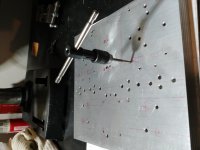
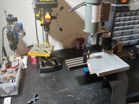
Chassis is milled where necessary.
a) didn't want to mill a lot - it's time consuming work and my milling machine is slow
b) wanted to keep it bulky, and retain as much metal as possible
One big disadvantage of this kind of chassis is servicing.
As you see all cables are soldered to the PCB from beneath.
In case you need to remove PCB to fix it, or change a resistor, it's pain in the neck.
Lots of work, but of course can be done.
Box with fins allows easier access to everything.
Yeah, I though about it many times, but there is not much to gain.It occurs to me that you could have milled or drilled in channels for water cooling in the slabs and clamped your MOSFETs the other way. Then have two tubes go to a separate water cooling radiator unit. Although the fins and fans look way cooler.
Lots of work, and you still need a fan or two. Plus water cooler with fins.
Volume wise - bigger then 2 CPU coolers, and more clutter.
But it might be OK for really hot-running A-class amps...
Another thought was - to built in water cooling fans, coolers, etc.. into the PSU, and just connect it to the chassis with 2 water tubes..
This way it could be re-used for other amps.
It's not Cu, I'm afraid 🙂Which brand/model is that copper finned one? Never seen that before.
It's Cu plated aluminum, generic cooler, but I replaced fans with Noctua silent ones.
Attachments
Thanks Hugh! Didn't have time for listening tests yet; just finished the chassis yesterday evening.Hi Minek123,
Now you have run your AN 40 for a few hours, maybe days, could you describe the sound quality? Are you happy with it?
Very professionally done, congratulations for a great job. Excellent two fans for four towers, economical cooling system.
HD
As soon as I'm done with listening tests, will let you guys know.

Impressive, minek123!
Are you able to convert the .lay file to gerber?
What speakers do you have?
rgds
Are you able to convert the .lay file to gerber?
What speakers do you have?
rgds
I can generate new gerber files if you need.Impressive, minek123!
Are you able to convert the .lay file to gerber?
What speakers do you have?
rgds
The original ones had few holes too small, and I had to -re-drill PCBs.
My speakers are JBL_STUDIO 590
Little bit over 6 Ohm..
But I have to warn you - this PCB is very dense, and does not support any terminals, headers, spade connectors, etc..
Just holes for cables to solder them directly. So it's not user friendly for traditional builds.
Also, it has two grounds - input ground, and dirty ground. They are NOT connected together on the PCB.
I always use 2 separate cables to connect PCB to common ground.
No ground lifting with a resistor.
It always worked perfectly for me. No loops, no hum, no resistor.
Feel free to modify lay6 file and make changes...
Attachments

Last edited:
Looks like I need a new PSU to fully test AN.
My 800W +/-80V DC psu can't cope with current.
I had to lower input AC (using autotransformer) to get output
+/-21V DC for AN, and it seems that my toroidal trafo thinks this AC voltage is too low to deliver current needed.
It's like going down from nominal 110V AC input, to 25V AC input.
It buzzes, and after 3 minutes with AN connected, blows built-in main line fuse.
Luckily it survives just fine..
This technique worked OK so far, for all amps powered from +/- 25V to +/- 80V.
My lab/test PSU (AIM-TTI INSTRUMENTS CPX200D) is 180W (when going downhill), so I can only test one channel at the time..
When I connect both channels, negative rail is sagging..
So, in conclusion - to run both channels I need to quickly put up together a new PSU.
I happen to have all the parts needed, for just such emergency 🙂
The 1st thing was for PSU to be 'outsourced' and connected
by cable. I wanted to do it for different reason - too many amps, too many PSUs.
Why bother ? - just have one PSU box, and use it for all amps.
I only use one amp at the time.
Very true, sounds like a plan!
I am using a 600VA transformer for both channels and it works fine delivering +/-28.5v at 1.7A.
- Home
- Amplifiers
- Solid State
- Alpha Nirvana 39w 8ohm Class A Amp