Hi Minek,
I do think your arrangement is good and clearly keeps things cool.
However, I'll discuss why we used plugs and wiring to connect the outputs.
Here were the reasons:
1. To accommodate passive cooling, cpu towers and other forced air methods, we needed to rearrange the outputs in different ways. For example, with passive cooling you might need to have the thermal centers at least 100mm apart to optimise thermal stresses on a long heatsink. For the cpu towers, very narrow positioning meant you could use one tower per channel - and two devices running at up to 60W EACH could be cooled by one tower designed for up to 120W dissipation. These are very different arrangement, and we had to design for it.
2. There is no instability on this approach due to long wires. I'd done a lot of work 25 years ago with IRFs mounted off the board, and there were never any instabilities, even though in those days I never used any but the IRFs. More gm mosfets are slightly more self-oscillatory, so we put on the snubbers to be sure. Optimally they should be mounted on the devices, hence the snubber pcb.
3. If there is an output failure, replacing them is a doddle. A few reconnections on the snubber pcb, and plug it into the main board and it's done - a single bolt, a few minutes of soldering and its' done.
A big issue with Class A is heat management. We are DIY, so we have to give a generic solution which will please everyone. This one works, and there are no down sides. You used your own approach - credit to you - and it seems to work. But you did design your own pcb, and we attempted to make a beautifull, SOTA designed pcb for other builders at low cost to save the inconvenience of doing their own.
Thank you for building the AN 40 and adding to the list of happy builders!
Hugh
Last edited:
Hugh, you are right. I follow your logic. Long wires (as shown in this case) will definitely
work - with snubbers and stoppers.
I wanted to keep everything simple, that's why I skipped wires, snubbers, pcb connectors,
clipping indicator, etc...
I always design my own boards, that's the best part of the project!
Also, my goal was something small - this amp has only 4 transistors + fets.
It's smaller than 'baby Aksa' 🙂 No adjustements, no drivers, no bias, not thermal tracking.
That's its beauty.
Kudos for designing it. It does sound great, the longer it plays, the more I like it!
I believe in measurements. Have anybody built AN with cpu coolers? Any temperature readings to share?
So far I guess only Andy is using CPU coolers for AN..
I have just a bit more wiring to do, before I can fire it up, minek. 🙂
Then, as I have a temperature gun, I can give you some measurements.
Yes, so far I think it is only me who is building an AN with CPU coolers - one per channel. I am building the 4R version - so:
* DC rails are nominally +/-20v ... maybe as high as +/-22v
* bias is nominally set at 3a (as a result of the resistor values used in the 4R circuit).
So each CPU cooler will have to deal with 120-132w of heat.
Guys, I have a question here regarding the current drawn from the SLBs.
For an 8ohm load, the bias current through the MOSFETs has been set at ~1.7a.
To make an AN capable of driving a 4ohm load, bias has been increased to 3a.
So what happens when the load is actually only 2ohms?
Does the AN circuit simply draw more current from its SLB?
So it might cause bias to be 4a? (In which case, heat dissipation becomes 160-176w.)
I highly doubt to see any fet in class A amp, connected directly to the cpu cooler, running any cooler than 70 degrees.
I'll let you know! 🙂
I've not had much experience with temperature guns but I'm assuming if I shine the 'red spot' on the edge of each MOSFET ... it will give me the temp of the MOSFET itself?
Whereas if I point the gun at the cast aluminium top of the CPU cooler (which has the copper pad in its base) ... it will give me the temp of the base of the CPU cooler?
Andy
Andyr thermo temp readers can be sketchy, make sure move the orientation around. ego parallel, perpendicular etc. You can see as much as 20C diff, just by turning the gun 45 degrees and looking at the same spot.
Jacques, where exactly did you measure your 50 degrees? Right at the fet plastic case, or at the metal heatsink?
Hi Minek,
The temperature sensors are taped on top of the heatsink.
Maybe I'll try directly on one output next.
Cheers,
Jacques
Hi Minek,
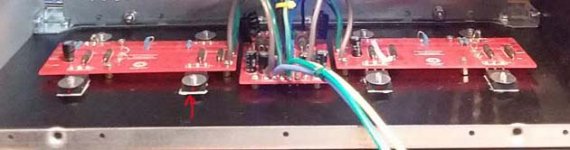
OTOH I understand your point too. To show you my own pcb you will see I used your technique!! But I was using a different forced air heatsink, a Conrad MF18-150, and it was custom for that heatsink.
Thanks for your thoughtful answer!
Hugh
OTOH I understand your point too. To show you my own pcb you will see I used your technique!! But I was using a different forced air heatsink, a Conrad MF18-150, and it was custom for that heatsink.
Thanks for your thoughtful answer!
Hugh
Attachments
That's true. They give different results depending on the color and finish of the surface.Andyr thermo temp readers can be sketchy, make sure move the orientation around. ego parallel, perpendicular etc. You can see as much as 20C diff, just by turning the gun 45 degrees and looking at the same spot.
Best, accurate results come from black ,matte surfaces.
Shiny aluminum will give LOWER temperature readings.
The best is to measure temp on the plastic case (back side) of the transistor, which is usually almost black, and matted.
Alu heatsink - I glue a small piece of black or blue tape on the surface, and take a reading from it.
I see at least 10 degrees LOWER readings from shiny Alu, than reality.
Black heatsink should be perfect.
If you are using metal sonda (sensor) to take measurements, use some heatsink compbound on it,
so it has better contact with metal surface.
minek I have found the hot spot, for vertical mounted is the top black matte and the sensor held perpendicular.
Is that one of Pappas' amps? 🙂
What's the temperature?
Last edited:
Is that one of Pappas' amps? 🙂
What's the temperature?
Ya, that was my first Class A build, it's an F5T V2 and, if memory serves, it ran around 55-60C. I gave it to a friend for Christmas, or I would fire it up and check.
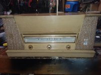
I have also built the M2X which runs a bit warm because I put it in and old school 50s radio chassis. She runs about 54-65C.
My J2 has large sinks and runs in the low 50s, MY AN monos have small sinks and runs a bit hot too at 57-65.
I have 3 Pass builds and they all run from about 50-65C. The M2X is dual mono and has four fans on the sinks because of the old chassis. Here's an image to get your mind around it.
Attachments
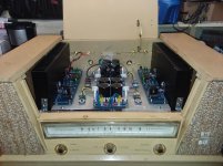
Beautiful build!I have 3 Pass builds and they all run from about 50-65C. The M2X is dual mono and has four fans on the sinks because of the old chassis. Here's an image to get your mind around it.
Beautiful build!
SHe was runnin to hot, so I took the side panels off which was just some partical board. I cut a big rectangle in them and put burlap over it to let the sinks breath and then installed fans to help a bit and now I can run it with the top down. 😀
SHe was runnin to hot, so I took the side panels off which was just some partical board. I cut a big rectangle in them and put burlap over it to let the sinks breath and then installed fans to help a bit and now I can run it with the top down. 😀
I think big heatsinks won't do much for amps with only 2 output devices.
Big heatsinks work very well for amps with several pairs of outputs, evenly spread over the heatsink surface.
I'm afraid for class A with 1 pair, active cooling of some kind is in order...
Instead of overloading and overheating 1 pair, better split output into 2 or 3 pairs.
These big heatsinks will work like a charm without any fans.
On other hand, I have a feeling these hexfets can run really hot if they need to.
I remember, X reported that once he forgot to keep fan running, and the amp survived just fine...
Not sure how long they will last though...
I think I'll stay with 20V rails for AN.
The amp works like a champ. Don't think I need more power..
These HP laptop bricks work really well. Need to case them in some nice enclosure, and it's done!
Last edited:
I think big heatsinks won't do much for amps with only 2 output devices.
Big heatsinks work very well for amps with several pairs of outputs, evenly spread over the heatsink surface.
I'm afraid for class A with 1 pair, active cooling of some kind is in order...
Instead of overloading and overheating 1 pair, better split output into 2 or 3 pairs.
These big heatsinks will work like a charm without any fans.
On other hand, I have a feeling these hexfets can run really hot if they need to.
I remember, X reported that once he forgot to keep fan running, and the amp survived just fine...
Not sure how long they will last though...
I think I'll stay with 20V rails for AN.
The amp works like a champ. Don't think I need more power..
These HP laptop bricks work really well. Need to case them in some nice enclosure, and it's done!
I like the idea of doing the supplies on the cheap, hell that's why we are all here because we want to save money and still have kick *** gear.
My rails on the AN are at 28V, it's just how the numbers worked with the SLB and my chosen transformers. Those IRFPs are rated to 150C!
https://www.vishay.com/docs/91210/91210.pdf
For me, the huge sinks make the case like something you would carry luggage in... I mean those cases get huge, and not only that, they are very expensive, by far the largest single cost in the build. You can go a lot of other directions for much cheaper and still get good results. I might build something for 4ohm loads and if I do, I'm going to get creative on the case and cooling.
Those IRFPs are rated to 150C!
I must disappoint you - 150 degrees is the max temp of the transistor JUNCTION -
the die itself, inside the case.
Junction temperature - Wikipedia
Not sure exactly how much higher it is than temperature of the case,
but I think I've seen an example - if case is running at 100 degrees, the junction temp is most likely maxed out already or almost maxed out...
To me, 85 degrees of the transistor case is absolute max, and I would not run any amp higher than that.
Last edited:
I must disappoint you - 150 degrees is the max temp of the transistor JUNCTION -
the die itself, inside the case.
Junction temperature - Wikipedia
Not sure exactly how much higher it is than temperature of the case,
but I think I've seen an example - if case is running at 100 degrees, the junction temp is most likely maxed out already or almost maxed out...
To me, 85 degrees of the transistor case is absolute max, and I would not run any amp higher than that.
Yes, I understand. 😛 It's still a crazy amount of heat. I don't let anything get to 70C in fact, I would be happy to see nothing over 55C, but getting there could get expensive, and I don't think it needs to happen. Class A is hot.
Exquisite layout and build, TT!
That is factory clean, it looks fabulous....
And how does it sound?
The question I ask is 'Does it make you weep?'
That is factory clean, it looks fabulous....
And how does it sound?
The question I ask is 'Does it make you weep?'
I think I'll stay with 20V rails for AN.
The amp works like a champ. Don't think I need more power..
But if you have 20v DC rails ... surely you need to use the res values shown in the 4R circuit? (There are quite a few resistors which have different values to the 8R - 27v rails - circuit.)
Andy
But if you have 20v DC rails ... surely you need to use the res values shown in the 4R circuit? (There are quite a few resistors which have different values to the 8R - 27v rails - circuit.)
Andy
My values are adjusted - they differ slightly from what Hugh published.
I published my own spice sim few days ago..
I simmed with 20V rails and 27V, and everything looked good.
Also, on the scope it looked all good with both voltages.
My idle current is 2.2A per fet (measured, with 20V rails),
and my speakers are 6 Ohms - so this is something in between..
- Home
- Amplifiers
- Solid State
- Alpha Nirvana 39w 8ohm Class A Amp