Your temperatures are rather low but maybe it’s not registering on the correct spot or proper emissivity surface.
My forehead is at 37 degrees, and, as I just found out - human brain runs at 20W.
Whole human - 100W, just sitting.
🙂🙂🙂
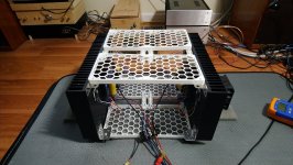
I made very small progress, was busy finishing some speakers. I 3d printed some grills and connected heatsinks, now only the font and back needs to be added. I am running it now at about +/-18 volts only, and with fans blowing at half the speed, heatsinks barely reach above 40 degrees C.
I need to build proper power supply, my rectifier bridges get hotter than amp!
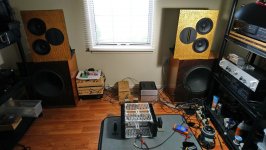
Listening for hours, with slightly better than test speakers, sound is addictive.
I need to build proper power supply, my rectifier bridges get hotter than amp!
Listening for hours, with slightly better than test speakers, sound is addictive.
Attachments
This is great idea to 3D print chassis components! And it looks very good!I made very small progress, was busy finishing some speakers. I 3d printed some grills and connected heatsinks, now only the font and back needs to be added. I am running it now at about +/-18 volts only, and with fans blowing at half the speed, heatsinks barely reach above 40 degrees C.
I need to build proper power supply, my rectifier bridges get hotter than amp!
Listening for hours, with slightly better than test speakers, sound is addictive.
How big of the components, size wise, can be printed
(using reasonably priced home printer) ??
Last edited:
we have an old lutzbot, max size is 250mm x 280mm x 280mm
for bigger objects, you can split, print separately and join together
lots of threads about unity horns and 3d
i am not very proficient in cad programming, i just download whats available and mod it
for bigger objects, you can split, print separately and join together
lots of threads about unity horns and 3d
i am not very proficient in cad programming, i just download whats available and mod it
Hi Adason,
You might want to consider using the LT4320 active bridge. No heat output and diode switch noise eliminated. You can make one using Prasi rectifier boards or make the SLB Class A PSU which has the LT4320 built in along with cap Mx. if you have not committed to trafos yet, the SLB requires extra 3v so size trafo secondary voltage accordingly.
You might want to consider using the LT4320 active bridge. No heat output and diode switch noise eliminated. You can make one using Prasi rectifier boards or make the SLB Class A PSU which has the LT4320 built in along with cap Mx. if you have not committed to trafos yet, the SLB requires extra 3v so size trafo secondary voltage accordingly.
Thanks for the info, I am aware of the active bridges. Never tried them yet, perhaps its about time.
The active bridge is one of the best things to happen to Class A PSUs. I am never going back to diode bridges.
You also gain an extra +/-1.2v headroom from same trafo (free several watts amp power boost). Like finding a $20 bill in the sofa cushions. 🙂
You also gain an extra +/-1.2v headroom from same trafo (free several watts amp power boost). Like finding a $20 bill in the sofa cushions. 🙂
The active bridge is one of the best things to happen to Class A PSUs. I am never going back to diode bridges.
+1 😀
Hi again Andy,
Measuring the ripple when your Nirvana is loading the SLB is sufficient.
Yes, the scope probe connects between the output rail and 0V. AC coupled.
If the observed ripple is low then you won't have hum coming from the SLB power supply.
Thanks, JH. 🙂
Have just put the AN boards back into the case, after replacing the Bourns pot for the DC offset with a fixed resistor.
Fired it up and took a pic of my CRO screen - with the CRO leads on the +ve DC spade on one of the AN boards and its 0v spade.
Attached pic is not very good (the waveform went across the whole CRO screen but, for some reason, my camera only picks up part of the waveform 🙁 ). But it's good enough to see that I am currently getting more noise than ideal. 😡 (Each graticule is 20mV.)
Would you agree?
Andy
Attachments

Andy,
Can you measure the voltage across your 100R resistor which replaced the LTP stage current pot? We are looking for 0.26V. If zero, as I suspect, it could be that your resistor is not connecting, and a very simple fix.
HD
Can you measure the voltage across your 100R resistor which replaced the LTP stage current pot? We are looking for 0.26V. If zero, as I suspect, it could be that your resistor is not connecting, and a very simple fix.
HD
Hi Andy,
What is the voltage drop across your cap Mx BJT? I usually adjust the pot for about 3v drop (the exposed pins of the BJT are easiest to probe). I find that the ripple after the cap Mx is about 1mV rms when the drop is of order 3v.
What is the voltage drop across your cap Mx BJT? I usually adjust the pot for about 3v drop (the exposed pins of the BJT are easiest to probe). I find that the ripple after the cap Mx is about 1mV rms when the drop is of order 3v.
X,
Andy has just found that the nmos on the bad module is blow, Vgs = 0V.
Not sure how this happened, but it is shorted.
Hugh
Andy has just found that the nmos on the bad module is blow, Vgs = 0V.
Not sure how this happened, but it is shorted.
Hugh
Hi Andy,
What is the voltage drop across your cap Mx BJT? I usually adjust the pot for about 3v drop (the exposed pins of the BJT are easiest to probe). I find that the ripple after the cap Mx is about 1mV rms when the drop is of order 3v.
Sorry, X - I'm not exactly sure. (And I would need to disassemble the mounting of the SLBs, in order to measure them.)
When setting up the SLBs, I:
* put an 80w-in-total collection of resistors across each DC rail in turn, to produce a calculated current draw of over 3a, and
* then adjusted the pot to get the lowest output DC level possible (that was equal in both channels). What that means in practice is that one pot is turned to the lowest voltage setting ... and the other is up a bit.
Even so, I've ended up with +/- 21.7v on each SLB module (not the theoretical 20v).
Why I wanted to know whether the noise that I could see on the CRO screen was acceptable enough is that - as you can hopefully see in this pic:

- I have 2 mains pairs (the traffo primaries) coming from the front of the case, down the middle of the case to the back ... where the mains switch/fuse/socket is.
As these mains wires are:
a. close to the '+ve rail' side of one SLB and the '-ve rail' side of the other, and
b. cross a number of earth wires
... I am worried that I will get induced mains hum.
If this happens, I will have to cover the mains pairs with an earthed braid (which I'd rather not have to do - as it's a bit tricky).
Andy
Last edited:
Hi Andy,
The output of your SLB under load should be at the circa mV rms level. It should look like a 120Hz sine wave in shape. There won’t be any peaky spikes like you show. Something is not right there.
I would use shielded coax RG170 or similar to bring your audio input from the back to the front. And keep it as far away from the trafo windings as possible. You have twisted pair there and that might work but still too close to trafo. I would not worry about the mains from IEC the trafo ad current is lower at 240v - so 1A?
If you can get your CRO probe tip to hook on the BJT pins are the heatsink that would be one way. They are covered in shrink tube though. Maybe scrape a bit off. That’s where you can see the ripple upstream vs downstream. And it should look something like this (4.4A at 35v and 3.1v drop across cap Mx):
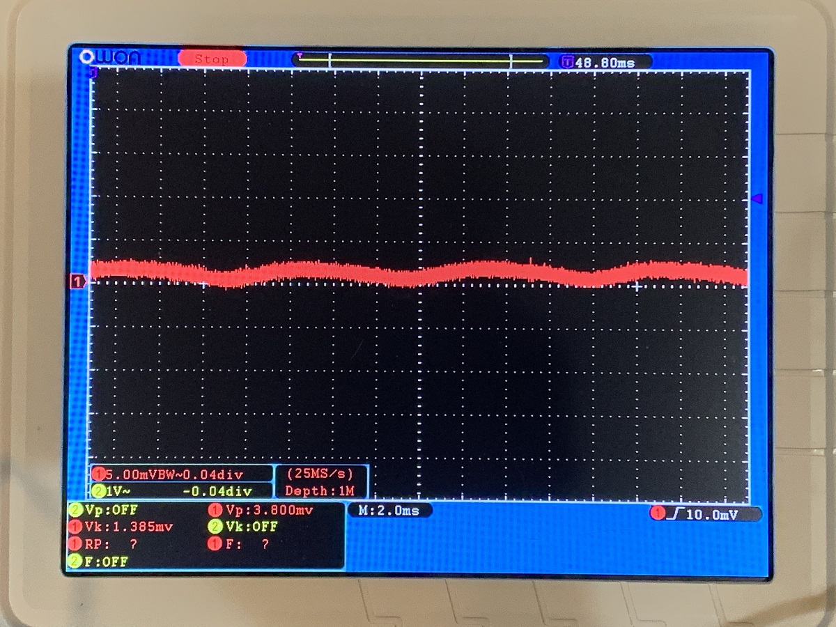
What do you all think of this as a chassis for the AN? The heatsinks look to be the right size. All cutouts and connectors provided except binding posts on back. $237 shipped.
BRZHIFI A60 series aluminum case for class A power amplifier|Amplifier| - AliExpress
BRZHIFI A60 series aluminum case for class A power amplifier|Amplifier| - AliExpress
I really like it, X. Very strong, sufficient cooling fins, lovely front (would need a VU driver circuit of course and good quality output/input connections at the rear.
HD
HD
Hi Andy,
The output of your SLB under load should be at the circa mV rms level. It should look like a 120Hz sine wave in shape. There won’t be any peaky spikes like you show. Something is not right there.
Yes, that's what I thought - a sine wave of a couple of mV, p-2-p, on each DC rail. (100Hz, here in Oz. 🙂 )
I would use shielded coax RG170 or similar to bring your audio input from the back to the front. And keep it as far away from the trafo windings as possible. You have twisted pair there and that might work but still too close to trafo.
The tps you can see are the connections between the front panel LEDs and the AN boards. I can't really get them away any further from the traffos than they are?
Could the nasty hash you can see in the CRO pic caused by the LED tps running for too long in the magnetic field close to each traffo? Do I need to use shielded coax for these LED connections, instead of tps?
If you look at my amp pic again, you can see my input-signal RCAs are at the outer sides of the back panel - so a very short path to the input 2-pin Molex on each AN board.
I would not worry about the mains from IEC the trafo ac current is lower at 240v - so 1A?
I would think each traffo primary current would be about 1.4a at 240v, no? 3a x 43v p-2-p is 130w so if the AN boards are 40% efficient then the total power draw through each traffo is 325w, right?
Could it be that this primary-winding current draw is inducing the noise we can see on the DC rails because it is running along one edge of each SLB board?
If you can get your CRO probe tip to hook on the BJT pins are the heatsink that would be one way. They are covered in shrink tube though. Maybe scrape a bit off.
Yes, I'll see if I can scrape a bit of heatsink off.
Andy
X - I have now solved the problem Hugh referred to in post #1212.
It was not the N-channel MOSFET that had blown - simply that the Wurth connector on the PCB wasn't making correct contact with all 3 wires going to the Snubber board! 🙁
Once again, I had not been able to lock the socket in the female header - so pushing it down onto the male part on the PCB must've made the sockets lift (so one or more weren't making contact).
That's the second time I've had this problem (if you remember, I burnt out an R15 when I first switched the SLBs, as a socket had lifted and wasn't making proper contact with Q12).
I think the design of the header is substandard; IMO, the engineer who designed it should've created a more effective socket-locking mechanism - those little, angled 'wings' are hopeless! 😡
However, the solution is simple - simply leave off the header and press each crimped socket onto its corresponding pin in the male section. The crimped terminal fits tightly around the pin - particularly after I put heatshrink around the socket / the end of the wire.
Note: this has the added benefit of stopping the copper wire in the exposed part of the crimped terminal from oxidising. 🙂
DC offset on this module is -2mV ... which is great.
So now I'll leave it on for an hour and take some heat measurements. (I've put some 'White-out' on the Al base of the CPU cooler and on the central copper pipe, at the other end of the fin stack - as per your suggestion.)
Andy
What do you all think of this as a chassis for the AN?
It looks good, it also has a wave pattern on the cooling fins,
cooling seems to be comparable to the 4U/300mm of Hifi2000.
I don't like the placement of the sockets, I prefer more a left and right placement for the channels than grouped together.
Last edited:
I don't like the placement of the sockets, I prefer more a left and right placement for the channels than grouped together.
I agree, Danny. 🙂
Also:
1. there's no fuse holder on the back panel???
2. the gold front is a bit OTT, to my taste. 🙁 (I like black fronts. 😀 )
Andy
- Home
- Amplifiers
- Solid State
- Alpha Nirvana 39w 8ohm Class A Amp