X
You can never get it right if you use 10 ohm resistors because there do gicve trouble.
the schematic of the current limiter schematic do work, or use a amp meter in series and 1 amp fuses or some lower like 800 mA.
The resistors do limit things to much.
set the 8,2 volts in the pcb and 1 Kohm resistor feed it, and the J310 jfets close to board or couple them thermally, setup for 10 volts and measure this over the 2.2k resistors who need to be 4.5 mA for each 2sk170.
The amp here is still on, for hours and stays stable, upload now some recorded music, it looks the amp sounds gray/hars but maybe this can also be the source like the pc output and youtube.
That you see stable VAS, let see the transistors do thermal runaway, normal when get warm the gate voltage needs to lower itselfs, this do the transistor on the irfp240 housing like with me.
regards
If I don't have J310 yet is there any need to use 8.2v Zener?
So J310 needs to be coupled to heatsink then?
I will build the regulated current supply. Looks simple enough.
Btw, I also notice the sound is harsh like crossover distortion - even at 1.3A bias. Something strange going on. What does sine wave input vs output look like? It sounds a bit like a class AB amp with very low bias - like class B so hear switching distortion.
Kees,
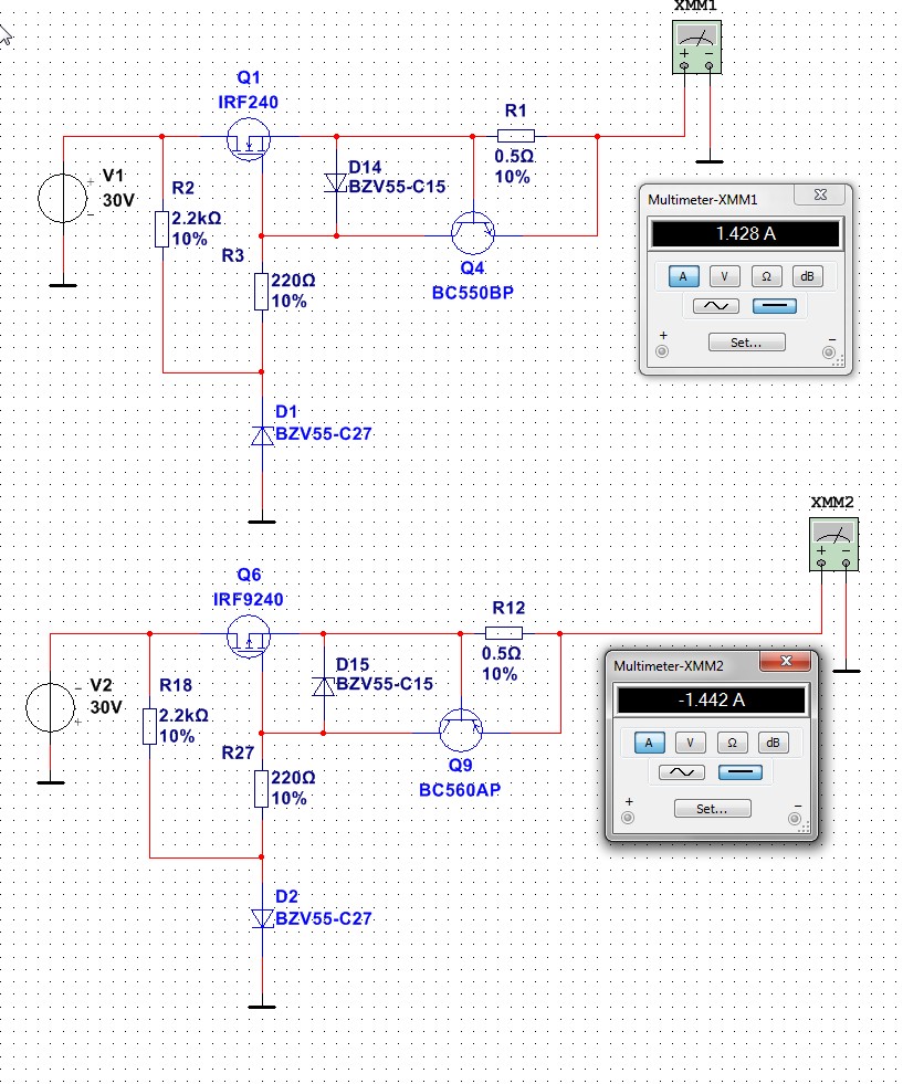
On current limit circuit - is the 0.5R used for current sensing? The 15v Zener is just gate protection, what is purpose of 27v Zener? Is there any voltage regulation or just whatever is applied at voltage source comes through? If I want variable current limit, do I replace 220R with 500R pot?
Thanks
Hi x
It is stabilized through the 27 zeners giving 25 volts, the 0.5R is indeed a current protection, it is simple but works oke, I have used airfp240 mosfet but a smaller one with lower voltage 60 or 100 volts but 10 a 15 amps is also of use.
Variable current limit can not done with a pot because it is low ohmage, but a step switch can be used with for example, 0.1 ohm, 0,2 ohm 0.3 ohm 0.5 ohm 1 ohm etc where 0.1 ohm is the highest current.
You can not adjust voltage, this is due to zener in it, but it is a nice protection for working on the amp.
The J310 can not de mounted on heatsink, she do work the wrong way, keep them cool by install with short pins to pcb, the 8.2 volt is only needed when use the jfets,, for a resistor use just the 15 volts, but with a resistor things get not better, so await the J310, maybe order some dn2540 to99 is a idea.
For me the sound, I think it sound some hars grainy, and I think it is because of the mosfets used, also I go change the feedback to full because these mosfets are quite non liniair who can give grainy sound, also it can be that I have to use to it, I have a hybrid amp where I am listen to for years, have to readjust.
I did discover some music sounds quite beautifull maybe some redordings did cause it, maybe when have a good amp bad recordings do are discovered more quickly.
regards
Last edited:
You discover also grainy sound, maybe as I think the VAS has high impedance Drain followers feeding a low resistance network, 680 ohm and 270 ohm in my case.
Or the ZVN type mosfets have to low idle, causing this.
I go reconect the feedback to full, outside pins used in stead of the inside pins, we have a common problem now, the sound is not well.
regards
Or the ZVN type mosfets have to low idle, causing this.
I go reconect the feedback to full, outside pins used in stead of the inside pins, we have a common problem now, the sound is not well.
regards
Hi Kees,
I have used the IRFP 240/9240 MOSFETs in many other amps and they are capable of low distortion beautiful sound (FH9, FH9HV, CFH7, VHEX+, Pass ACA, Pass M2, Piersma JFET Circlophone) - so the MOSFET is not to blame. It may be indeed how you drive them. They like low impedance drive and typical is 220R, and I have used as low as 10R gate stopper resistors from VAS. Some music does indeed sound free of distortion, but is similar in behavior to crossover distortion. Female voices and piano in particular show the distortion more than say, jazz horns.
Regarding the current supply, a TL431 programmable shunt voltage ref may be used to get variable voltage then I think (35v max)?
So which feedback pin should I use please show diagram.
https://youtu.be/0P8IfKOheto
first sound, local feedback, sounds like crossover, you are right, with full feedback I get the same.
What I also discover without the irfp voltage the drivers do have bad distortion, so people here, let here the faults I made. I think it can be through the drivers VAS are drain followers, so have higher impedance, idle on 30 mA each half.
Sounds a little compressed, so can be a problem.
X I go measure the distortion with the pc maye I can see what happens.
I did see smoke, coming out the amp, was forgotten to tight the bold of one irfp240, and did cook.😱
regards
Last edited:
Is distortion fixable via mods to component values or new topology/layout needed? I have not tried the other feedback pin - whatever you call it?
Hi X
Maybe the ZVN 4424A is the cause, this mosfets can stand 40 volts gate source voltage and she are 500 milliwat 500 mA, but in my amp she do just 20 mw dissipation while the 2sk170 do 60 mW.
I can try other mosfets or change the zener so it eat more idle current, 5 mA is for this fet maybe some to small getting crossover.
In sim however it is quite clean.
regards
Oh that makes sense. Input stage should be biased class A if possible. Can we use another pair of 2SK170 rather than ZVN4424G?
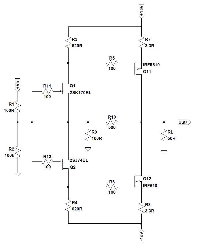
X I have look at what happens in the amp, my idea is that the high impedance of the differential input amp do make trouble when drive the mosfets irf9610 the capacitance of them do shut of this stage and go from 40 volts to 7.8 volts, (without feedback only input section) this drop is a cause of the grainy sound who look at crossover, but is in fact compression like distortion.
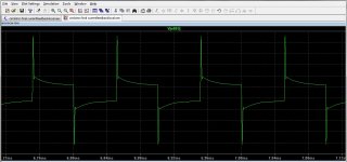
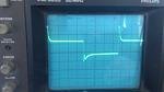
So we need a impedance converter there or something so we can drive the irf9610 driver section properly, it give not bad overshoots also.
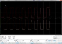
But for the feedback lines see pictures.
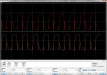
The scope pictures is first with no load on the source of zvn4424a and second is with gates connected to zvn4424a and results. (50Khz square)
regards
So we need a impedance converter there or something so we can drive the irf9610 driver section properly, it give not bad overshoots also.
But for the feedback lines see pictures.
The scope pictures is first with no load on the source of zvn4424a and second is with gates connected to zvn4424a and results. (50Khz square)
regards
Attachments
Last edited:
So we need a impedance converter there or something so we can drive the irf9610 driver section properly, it give not bad overshoots also.
Kees, my F5 headamp uses 2SK170/2SJ74 to drive IRF610/9610 directly in pure class A very well. There is absolutely no distortion. Please look at resistors used here and see if there are changes to current layout values that may afford this. To be sure, 2SK170/J74 can driver IRF610/9610 perfectly well.
I wonder if I can even make the F6 HA front end to use as driver for the power stage of your Circlotron? No CCS needed even.
X that is a headphone amp, it is quite different with a big swing audio power amplifier because we needs more swing and topology is different.
I have a other circlotron wo do look like yours, but with only Nfets, because it are two half amps.
How much current flows through the Jfets 2sk170? you have current feedback I see.
regards
Here is the LTSpice file - I only have Tina so can't run it. You can get currents in there. I am guessing 15mA range?
http://www.diyaudio.com/forums/atta...d1427197670-f5-headamp-f5-headamp-irf-thd.asc
http://www.diyaudio.com/forums/atta...d1427197670-f5-headamp-f5-headamp-irf-thd.asc
X I have done like you did, get more current in LTP who drive the VAS mosfets.
Still overshoots, and this makes things hars.
I go look at a LTP who has low impedance output to drive the mosfets.
Mine amp is now on the whole day, and idle stays rocksolid on 45 mA (plus and minus 10 mA.) but when cold start it runs quite high the first 30 seconds, then it drops because of the sensor transistor get warm, as we now now these low on mosfets need really a fast tracking transistor who has to be glued on the place where tekst on mosfet is and not under the bold.
regards
Attachments
Nice to see your creation up and running.
Under what load conditions did you test the amp?
Little late
I did test with a 4.7 ohm 5 watt resistor.
But has some distortion in amp who looks like crossover, I go uograde the current through 2sk170 zvs mosfets as X suggest and see what happens.
Looks like the capacitance and miller in the drainfollower dor disturb things of the diff amp output who is high impedance, maybe a ccs in stead of the resistors will help.
regards
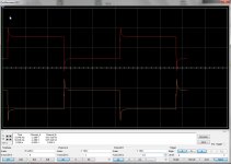
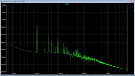
I have test on sim with ltspice, why there is so a nasty distortion, it is waht X say, the current in the long tail pair is to small,zvn mosfet just do dissipate 14 milliwatts.
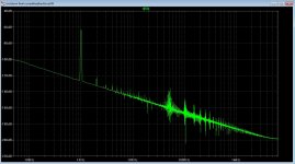
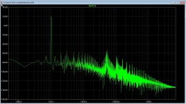
see the FFT what the differences are. Picture one is wuth long tail pair has higher idle current of 9 mA, but when higher or lower it get trouble by make more distortion. The first picture is how circlotron is now, the 2.2k resistors have way to high impedance to drive irfp 9610 capacitance, because this fet do amplify the capacitance do also, (miller).
regards
Attachments

Last edited:
You mean increase from 10mA to 18mA in LTP is what we need to do get lower distortion? Would changing 2.2k current limit resistors to 1k do the trick (plus adjust pot located at the end where the negative fail is)? Zvn4424 is a vertical MOSFET capable of 1.4amps in a TO92! Vertical MOSFETs require higher currents to stay away from crossover distortion. It would seem that 2SK170's (capable of 15mA) would have been a more linear choice. Not sure if pin compatible between two.
You mean increase from 10mA to 18mA in LTP is what we need to do get lower distortion? Would changing 2.2k current limit resistors to 1k do the trick (plus adjust pot located at the end where the negative fail is)? Zvn4424 is a vertical MOSFET capable of 1.4amps in a TO92! Vertical MOSFETs require higher currents to stay away from crossover distortion. It would seem that 2SK170's (capable of 15mA) would have been a more linear choice. Not sure if pin compatible between two.
X
I have lower the LTP 2.2k to 680 ohms, and a current of 8 mA, the fact things distortion so much is because the LTP current feedback steal current and so crossover occur. It as you say in yours, it did sound well, and because your headphone amp has also a current feedback who looks at mine it make sense.
with this modifications we get better, however I think the CCS needs to be a PN4391 or a DN2540 mosfet.
I go today because it raining soon make the modifications here, now I have in ltspice harmonics -80dB down.
I have two schematics having differend feedback resistors.
regards
Attachments
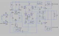
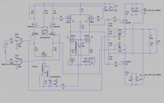
X I have look intensively to the ampplifier and we have a problem with the cascoded long tail input pair, the impedance is such high that the capacitance give the problems, LT spice see it better as multisim but it looks like.
Removing the gates and sim then give a nice square, what we need is a low impedance driver for the irfp 9610 between the gates and the long tail.
I have make the resistors smaller and now it is 680 ohm impedance still dispite the sim give -80 dB distortion figures do not mean it sounds well.
That your headamp do well is because it is not a long tail input, but just a drain follower driver who is not so high in impedance and so can drivce the irfp who also do just some volts .
Here the sim and real time, I get uge overshoots because of the high impedance of long tail pair seeing capacitance mosfet who is in fact need current.
regards
Attachments
Last edited:
The way to drive this would be to use Vzaichenko's current driven topology used in VHEX+ amp. It's a LTP input but requires quite a few TO126 KSA1381 and KSC3603's to do.
Example of a preamp/headamp with that topology here:
Example of a preamp/headamp with that topology here:
It's sounding like the current PCB may not salvageable? I wonder why the sims showed such good performance? Was it a mistake to base performance on Multisym vs LTSpice or Tina? We would not have gone to PCB fab otherwise?
- Home
- Amplifiers
- Solid State
- allFET circlotron