It's a cement filled white ceramic one - rated 10w I think. I have a proper 25w aluminum cased one mounted on a heatsink resistor I could use for long term testing.
I don't know how different IRFP250's are. I will switch to Digikey sourced IRFP240's tonight and see if that helps. I will also add BD139 temp compensator.
It's fun and I learn a lot more when an amp doesn't work the first time.
I wonder if 0.33R Supply resistors on IRFP pins leading to driver would help? Maybe that would dampen oscillations if that was the source?
If it did oscillate I have seen that on the scope, it does not here. the bd139 will give to much causing overcompensation, here it is stable on 500 mA it walks between 480 and 520 mA. but only with fan on it, removing this will cause a drop to 120 mA, so that is overcompensation for shure.
0.33 R resistors need to be on source for degeneration and so less drift in idle current.
The BD139 react also to slow in this amp, I think we do need to use a NTC and a paralell resistor as planned because these are a lot faster. are also used in smps
these days however where to find 22 ohm types or maybe even 10 ohms, who can be mounted on the mosfets.
Did you use the caps in the amp, in the feedback line? you can also try to switch pins of feedback to full middle pin to other side outside pin and vica versa and see what happens.
I still am unshure of the mosfets if she are genuin.
regards
Last edited:
I have seen yellow LED in series with BD139 to remove over compensation for IRFP240.
That is only for low current driver stages, here there is 60 mA I think a led will not like that. I did try a 22 ohm resistor not effect still to much, and to slow before it act, (then it is already in amps of idle.)
I go on the couch, rest because it is late here.
I put a question elsewhere for advice on diyaudio, like on original mosfets or not,.
regards
I have track down the cause of the idle drop when I remove the fan, the zenerdiode D3 for the current source do heat up and cause a drop, if this is so sensible then we need good 1 watt zener here to prevent this drops.
Or use that zener as a temp sensor buried in heat sink?
Then it work maybe to overcompensated and to late but is a idea.
the Jfet CSS I have did gas a little so it cool down, these are even more sensitive dropping the idle current of the irfp right away into the 1.6 ampere region and switch off the supply, that is why the fan did work, we need some work there, stay tuned.
And yes, fan problem tracked, the zener did a little, but the jfetsQ12 and Q11 did a lot, she do get warm because of dissipation, to much in fact so need
to get lower zener, like 9,2 volts or so,
regards
Last edited:
I have lower the 15 volts zener D3 to 8.2 volts making a lower dissipation for the jfet current source, now I can adjust to 850 mA and it run to 900 and then drops again because the transistor get warm, it has for shure overcompensation.
Now we have the cause, I think the PN4391 will do better, or I use a DN2540 as top mosfet where more dissipation occur.
Now we have the cause, I think the PN4391 will do better, or I use a DN2540 as top mosfet where more dissipation occur.
X
I had right about the mosfets, I did now put in the irfp240 and yes, these do not run like hell, but do as I think she do, run slowly while warming heatsink, I have small heatsink so i coo with fan, I have now without a bd139 but just with it as in sim who did predict it compensate on some matter, well, with a fan, and the current on 1.20 amps, it stay ther withing 1.20 and 1.25 amps.
The ccs in the input diff stage is temp sensitive, it let get down the idle when I do warm it, here we need a good ccs who do not act terrible, like one with a led is temp stable like you menion early, but when I use a dn2540G it do fine also and stand 150 mA.
Now for shure mine irfp250N are not oke, these run to much who do not fit. Now I have the irfp240 in it and these do much better, just step up slowly the current as it has to be.. Maybe the irfp are igbt,s reprinted, but then very good done, terrible how much chinese do rip us off it is not good for them economics on the long term..
My irfp240 are rebufisched or how you call that, seen on the littma damage on house, but she are good and genuin I think.
regards
Attachments
I did set after cool down set up the amp again, it did start with 720 mA and did run in just 50 seconds to 1.21 amps and did stay there happenly, yes with a coller because I have just a small heatsink of 9 x 15 cm.
I think just some small correction is needed, not more, will go have a happy end I think.
regards
I think just some small correction is needed, not more, will go have a happy end I think.
regards
Are you saying we need DN2540G where you said J310's were to go? I too wonder if refirbished IRFP240's are fake and actually IGBT's. Or is it that performance of 250 is markedly different from 240?
I see you have a 1N400x on a flying lead where NTC was supposed to go? I am glad it is now stable.
So looks like I need to confirm genuine IRFP240's installed. Then use DN2540G for J310's. What about BD139 temp sensor on body of IRFP240? Do I still need that?
I see you have a 1N400x on a flying lead where NTC was supposed to go? I am glad it is now stable.
So looks like I need to confirm genuine IRFP240's installed. Then use DN2540G for J310's. What about BD139 temp sensor on body of IRFP240? Do I still need that?
Are you saying we need DN2540G where you said J310's were to go? I too wonder if refirbished IRFP240's are fake and actually IGBT's. Or is it that performance of 250 is markedly different from 240?
I see you have a 1N400x on a flying lead where NTC was supposed to go? I am glad it is now stable.
So looks like I need to confirm genuine IRFP240's installed. Then use DN2540G for J310's. What about BD139 temp sensor on body of IRFP240? Do I still need that?
Hi X
The dn2540G is a small to92 package fet, it do fine as a ccs, but it has just like the other a inpack on temperature, not so bad when we do get the Vbe right and I have quite nice action, when I setup 500 mA without fan it get hot and it do drops to 340 mA, this means it overcompensates.
The in4007 diode is not used, I have use the transistor on the body, however with a fan it do almost wel without a bd139 or other transistor, starting at 820 mA and stabilizes on 1.21 amp in just 18 seconds but in real live without a fan we need the transistor sensor, or maybe a NTC who also do well.
Some advise me to gleu the transistor on the body where tekst is, and not under the bold because oth thermal resistance there and so later action of sensor.
These irfp240 are shure oke, she behave like it has to be.
I get the PN4391 soon these jfets can give more current and are a good fit, maybe a combination with dn2540 so it is thermally stable, but this is not a big issue power idle is.
regards
Last edited:
Now it do stay stable with fan, without it get hot and then ilde current drops, so it act normal because my heatsink is way to small, no problem with thermal runaway anymore.
the Jfets J310 or PN4391 can be used, or the stronger dn2540 who is available and J310 and PN4391 are old.
I have put it onfor hours settings at 500 mA at last 4 hours later it wa climbed to 513 mA, not bad at all, without the fan it stays stable until I can not touch the heatsink anymore then it drops, maybe also because of the fet get very hot.
Mine irfp250n are not oke because she are very unstable, and not possible to compensate, maybe because of the fet behavior I do not now.
So we are on track again.
X a mje 340 is also a nice transistor for tracking, but I go seek a ntc, ah can mucho better be adjusted onb every mosfet, need very low ohmage because a half ohm give already several hunders of more idle current.
regards
Last edited:
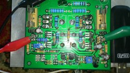
I replaced with genuine Vishay IRFP240's and am using BD139 temperature comp as you showed in diagram. I still have resistor current sink on input stage. The bias walks around a bit at first but after heatsink warms up seemed stable. With safety resistors in place and running 500mA still suffered thermal runaway as MOSFETs got cooked after longer period. This time 2 minutes then all of a sudden dead. Looking at dead MOSFET you can see it got so hot it oozed molten solder out of its joints onto silicone thermal pad. I did not change 15v Zener to 8.2v for D3 as I am using reisisfor for CCS so did not think it mattered. I think I need to wait for your final schematic and part stuffing guide.
Last edited:
I replaced with genuine Vishay IRFP240's and am using BD139 temperature comp as you showed in diagram. I still have resistor current sink on input stage. The bias walks around a bit at first but after heatsink warms up seemed stable. With safety resistors in place and running 500mA still suffered thermal runaway as MOSFETs got cooked after longer period. This time 2 minutes then all of a sudden dead. Looking at dead MOSFET you can see it got so hot it oozed molten solder out of its joints onto silicone thermal pad. I did not change 15v Zener to 8.2v for D3 as I am using reisisfor for CCS so did not think it mattered. I think I need to wait for your final schematic and part stuffing guide.
Did you remove the 10 ohm resistor on board who is parallel with bd139?.
Mine do wel, not a sign of thermal runaway, but one thing I did need to do, the CCS is really needed because I did get real jumps to high amperage.
Do make your mosfets good kontakt with heatsink? this is very strange, I did get unpredictable results when use a resistor, but then without the zener diode, I did get to 8.2 volts because of limiting the dissipation in Jfet causing a idle drift, using this on heatsink do not work because it go to wrong direction and is to much overcompensated.
Why you let the fets burnout? do you not have a meter so you can watch the current, I do switch off on 1.5 amps, the supply does.
You can make a simple supple with protection with a mosfet a zener some resistors and a limiting transistor.
regards
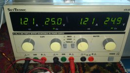
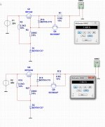
X here a very simple but effective current limitor supply.
with 0.5 ohm between base and emmittor give 1.4 amps max making the bigger in ohmage wll give lower current.. old and simple design block zener voltage if transistors go on.
never again blow up resistors.
I have now still the amp on, says as a rock around 580 and 610 mA with fan and small heatsink, whe remove the fan it go after 5 minutes or so drop in idle current when heat up the heatsink go to 480 mA but when I do nothing the heatsink get to hot even dropping further, so not a thermal runaway but just because a to hot heatsink who is quite small.
Do I set to 250 milliamps it stays stable also but now without the fan because then the heatsink is big enough.
You need to put in 8.2 volt zener 1 watt!! and proper Jfets close to pcb so temp is not so impacted who it does not, maybe we need to search a temp stable CCS here, but as for now it has little impact that is why I use 8.2 volts for little as possible dissipation.
Or do I have laterals? I think not because when cold it runs away until heat of body warms the transistor, I go try later after remove it from transistor what it does then.
regards
regards
Attachments
Last edited:
I have tryed to loosen the bold of the irfp240 and his transistor sensor, welllll it go run as hell when I do that, so it is a hexfet for shure, the sensor do work as I did already saww.
The amp is on now for 1.5 hour, without problems and with sound.
The amp is on now for 1.5 hour, without problems and with sound.
Did you remove the 10 ohm resistor on board who is parallel with bd139?.
Mine do wel, not a sign of thermal runaway, but one thing I did need to do, the CCS is really needed because I did get real jumps to high amperage.
Do make your mosfets good kontakt with heatsink? this is very strange, I did get unpredictable results when use a resistor, but then without the zener diode, I did get to 8.2 volts because of limiting the dissipation in Jfet causing a idle drift, using this on heatsink do not work because it go to wrong direction and is to much overcompensated.
Why you let the fets burnout? do you not have a meter so you can watch the current, I do switch off on 1.5 amps, the supply does.
You can make a simple supple with protection with a mosfet a zener some resistors and a limiting transistor.
regards
Correct, no 10R resistor in path just BD139. I can only monitor current with 10R safety resistors it's when I remove them that there is trouble. Maybe I need to put some 0.33R resistors in their place and use that as current monitor?
My heatsink thermal contact is good - whatever is state of the art using silicone pads on a big aluminum heatsink and clamped down with force from 4-40 hex head cap screw. BD139 is clamped on top of MOSFET with same screw.
Thanks for current limiting circuit. That will take a small vero board and need to be clamped on same heatsink. Maybe I need to make it as a lab bench variable current PSU?
Is the 8.2v Zener needed to limit current in the ZVN4424G or in the J310 (which I don't have yet)? Maybe the CCS is needed to prevent runaway? I did monitor gate voltage to MOSFET and do not see anything strange when MOSFETs blow up. Shows steady 5.4v voltage to IRFP240 gate pin. So I think the input stage and VAS driver stage are stable.
Let me order more IRFP240's. Just burned out my last one. Will need extra to make current limit supply.
idle setup from cold to warm, you see that it do stabilise.
https://www.youtube.com/watch?v=TYHHfgpYx-0
https://www.youtube.com/watch?v=TYHHfgpYx-0
X
You can never get it right if you use 10 ohm resistors because there do gicve trouble.
the schematic of the current limiter schematic do work, or use a amp meter in series and 1 amp fuses or some lower like 800 mA.
The resistors do limit things to much.
set the 8,2 volts in the pcb and 1 Kohm resistor feed it, and the J310 jfets close to board or couple them thermally, setup for 10 volts and measure this over the 2.2k resistors who need to be 4.5 mA for each 2sk170.
The amp here is still on, for hours and stays stable, upload now some recorded music, it looks the amp sounds gray/hars but maybe this can also be the source like the pc output and youtube.
That you see stable VAS, let see the transistors do thermal runaway, normal when get warm the gate voltage needs to lower itselfs, this do the transistor on the irfp240 housing like with me.
regards
Kees,
On current limit circuit - is the 0.5R used for current sensing? The 15v Zener is just gate protection, what is purpose of 27v Zener? Is there any voltage regulation or just whatever is applied at voltage source comes through? If I want variable current limit, do I replace 220R with 500R pot?
Thanks
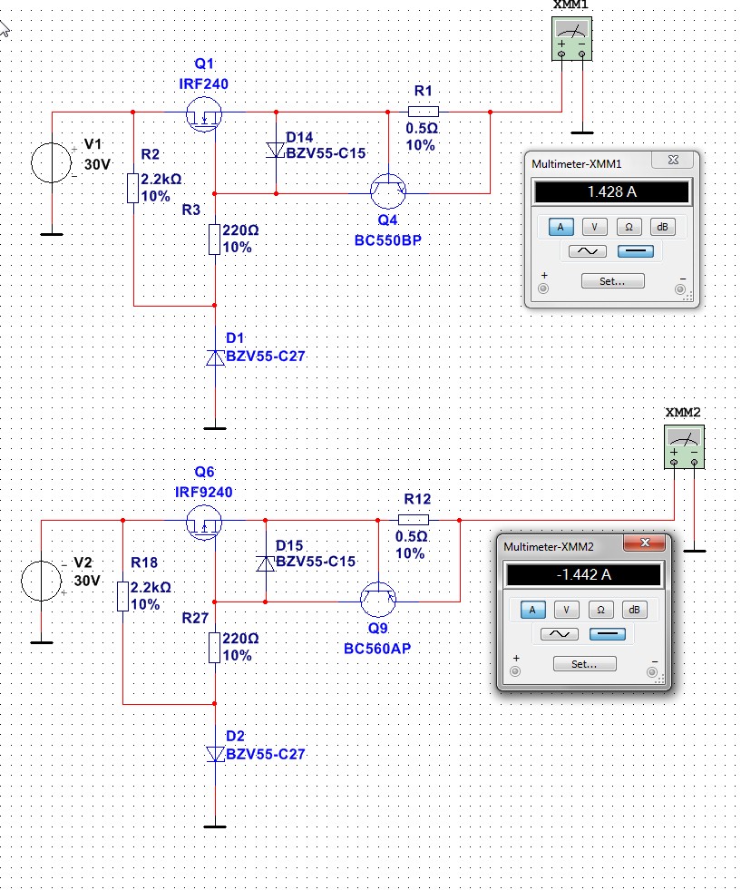
- Home
- Amplifiers
- Solid State
- allFET circlotron