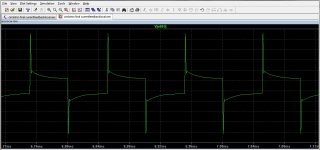
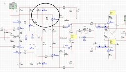
For this amp, the sims show low distortion, but let show also the peaks in the longtail to irf9610 mosfets and here excists because of miller effect a problem, It sound better with the changes, what proof it is in the long tail, we have to go from high to low impedance here to drive the irf properly.
The fact that sometimes the 2sk170 can drive a big mosfet is because it do in sourcefollower mode there the capacitance is less important.
It sounds grey in my eyes wit still crossover like distortion, it sound for me like the re is a restriction somewhere and that is the long tail who normally does nice, or the feedback network do make trouble, I can try to connect to gates and listen.
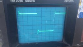
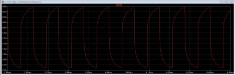
Photo 1 I have also on scope also, on the gates of the irf9610 it means there is not enough current to drive the capacitance give restriction, but the distortion is -80dB 😡
regards
The fact that sometimes the 2sk170 can drive a big mosfet is because it do in sourcefollower mode there the capacitance is less important.
It sounds grey in my eyes wit still crossover like distortion, it sound for me like the re is a restriction somewhere and that is the long tail who normally does nice, or the feedback network do make trouble, I can try to connect to gates and listen.
Photo 1 I have also on scope also, on the gates of the irf9610 it means there is not enough current to drive the capacitance give restriction, but the distortion is -80dB 😡
regards
Attachments
Last edited:
Kees
Just my thought ...
if input cascoded diff. pair works OK alone but loose on performance when is connected to gates of IRF9610 which are connected as drain followers,
than why don`t you replace U2&U3 with another pair of IRF610 but now connected as source followers sitting on top of U5&U6 , I think that will be very good pairs of buffers/drivers for circlotron power bridge ,
but than the question is ,do you loose to much OLG in this way ?
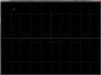
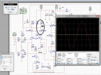
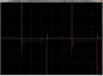
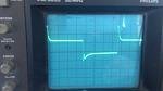
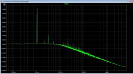
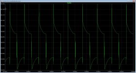
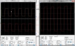
Here a sim of the long tail pair without gate driving and one with gate driving, it looses amplitude to get just 100 mv and without 2 volts and a perfect square without overshoots. Thirth photo is also on scope visible, big overshoot problem and this make amp very bad sounding, all is it in my case not that bad at all, so there is maybe a solution who I go seek for, the long tail get here a short tail of that mosfet driving.
Solutions with wilson current mirror etc.
When I listen longer the amp has quite a lot of detail, that is the only positive on music right now.
regards
Solutions with wilson current mirror etc.
When I listen longer the amp has quite a lot of detail, that is the only positive on music right now.
regards
Attachments

Last edited:
Kees
Just my thought ...
do you loose to much OLG in this way ?
Very goog thoughts anat, it is what I also did think because the drainfollower amplicates the capacitance also as miller effect, I am afread that the open loop get to small for removing distorting, I did think of what is on picture this can also be done with a mosfet for impedance translation>?.
regards
Attachments

Well ...
maybe will happen quit opposite, distortion will actually significantly fall down if you insert those source followers/buffers/drivers ,
I think than your circlotron SS amp will be topologically exact copy of Atma-Sphere OTL tube amp if you insert in proper way those IRF610 connected as source followers-buffer/drivers in-between cascoded diff. input stage and circlotron OPS , but must say that those Atma-Sphere amps usually works GNFB free OK,
any way if you decide to use those source followers as OPS drivers be sure that they are biased in A class of operation for lowest distortion , than OPS can be biased in cool a/B class , not necessary in hot pure A class ,
further you can remove R18&R19 (680R) and in that place to insert zener diodes as protection for IRFP240C gates ,
be sure to invert balanced GNFB lines ! ,
problem with that Grounded Gate driver connection is source very low input impedance which will again overload the signal from diff. input stage , is not good again .
Well ...
maybe will happen quit opposite, distortion will actually significantly fall down if you insert those source followers/buffers/drivers ,
I think than your circlotron SS amp will be topologically exact copy of Atma-Sphere OTL tube amp if you insert in proper way those IRF610 connected as source followers-buffer/drivers in-between cascoded diff. input stage and circlotron OPS , but must say that those Atma-Sphere amps usually works GNFB free OK,
any way if you decide to use those source followers as OPS drivers be sure that they are biased in A class of operation for lowest distortion , than OPS can be biased in cool a/B class , not necessary in hot pure A class ,
further you can remove R18&R19 (680R) and in that place to insert zener diodes as protection for IRFP240C gates ,
be sure to invert balanced GNFB lines ! ,
problem with that Grounded Gate driver connection is source very low input impedance which will again overload the signal from diff. input stage , is not good again .
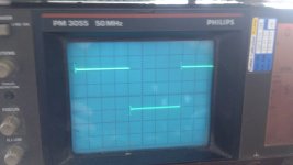
I did look at other designs of me and all have the overshoo problem when drive a drain follower, the grounded gate driver can be inverted so drain is on diff amp.
I do after listening have to say it has pretty much detail, hear room, ver much room in music, however it give a overdrive kind of sound, like with a guitar overdrive but then much less afcouse.
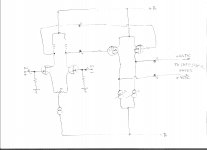
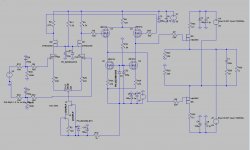
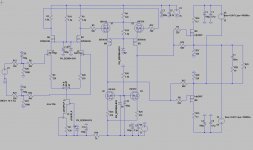
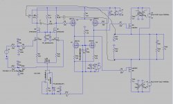
here a schematic with such grounded mosfet or in this case i did need a voltage source on gate to let it work, this amp did give very low levels of distortion, and it has only local feedback loops.
This has also the source on the diff amp dut the other side is high ohmage driver side and so I have remove the capacitance and miller, however also here the 2sk170 did give some overshoot, but can be corrented with cap.
This idea I go test in the amp.
When I remove the 680 ohm resistors the amp do not work anymore, missing referende to ground.
regards
Attachments
I did see when connect the diff amp to gates of drain follwers the signal drops from 4 volts to 20 mV that give afcouse compression distortion, as so sound it in my ears, but some music sound wel with it.
regards
regards
Ha I do see crossover distortion in the simulation on one part of diff amp.
As X say it sound as crossover, that make sense.
Also big overshoots, so have to see how to correct that.
The special amp needs more polish then I thought.
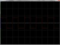
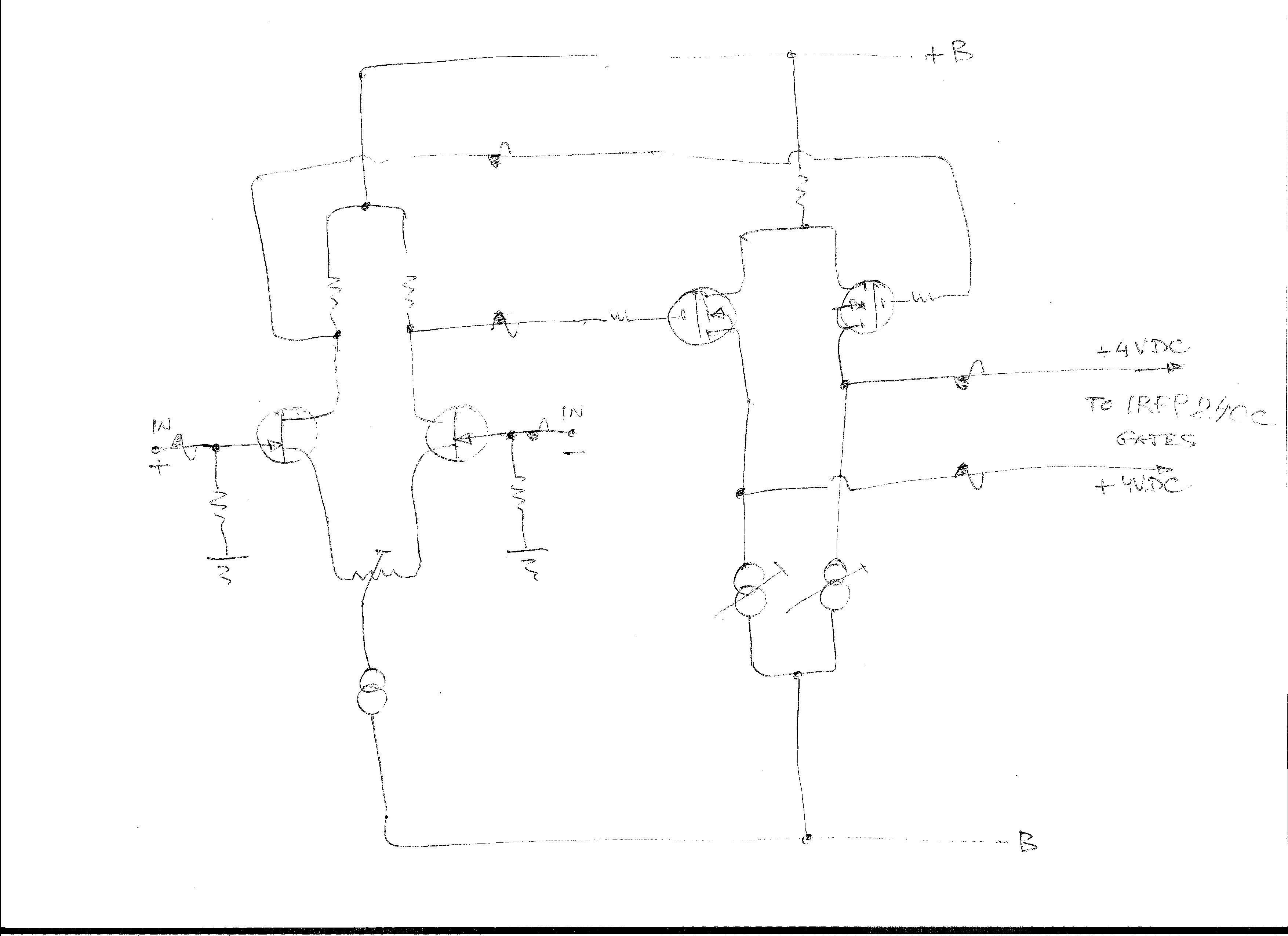
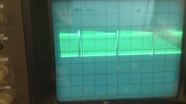
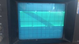
Banat, I did try the grounded buffer, it do limit overshoots as seen in picture 2 and 3. 3 is without buffering. Something strange here, and a need for capacitors to limit speed.
I did measure on the LTP cascode, the output do see not the overshoots in sim but see a nice square there.
Hmmm when use a balanced driver the crossover is gone, it is only on the jfet who is on ground with unbalanced drive.
regards
As X say it sound as crossover, that make sense.
Also big overshoots, so have to see how to correct that.
The special amp needs more polish then I thought.
Banat, I did try the grounded buffer, it do limit overshoots as seen in picture 2 and 3. 3 is without buffering. Something strange here, and a need for capacitors to limit speed.
I did measure on the LTP cascode, the output do see not the overshoots in sim but see a nice square there.
Hmmm when use a balanced driver the crossover is gone, it is only on the jfet who is on ground with unbalanced drive.
regards
Attachments

Last edited:
Kees
input VAS crossover distortion can be triggered with drivers drain followers configuration which can overload input VAS stage ,
here`s simplified building block with drivers configured as source followers , where
-DC current via each IRF610 driver need to be at least 10mA or even more ,
-stable around 4VDC or more on the gates of IRFP240C will determine desired quiescent current for OPS .
Attachments
I think this should work. This is resembles how F5 headamp is driven.
This is how it works X I have de crossover when unbalanced input is used, see the sweep it is on that side distorted, Mybe I wind a trnasformer to see wthat happens when using the as unbalance to balance.
A headamp is a low level amp, it give just some volts, here we have swings to 25 volts and it other reality.
Pictures are teken from gates irfp 240, irf9610, a sweep on output, a sweep on the resistors 2sk170 cascodes where one is distorted because of unbalance input.
Thanks for thinking with me, we keep trying.
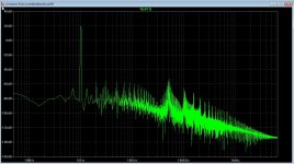
ON last picture we see a peak, but this get into squares in previous photo after set idle of 2sk170 and zvn higher.
regards
Attachments
Kees
input VAS crossover distortion can be triggered with drivers drain followers configuration which can overload input VAS stage ,
.
Excacly, that is what going on here unfornanely.
The setup of the follower has to be done in sim, I go try if I have enough open loop left when I do this, because then only the input diff amplified level is present.
regards
Hi X and Anat
I have did some sims and a impedance mismatch is going on, a bad one because it is capacitance who make the trouble because of a drain follower who is some amps.
Trying a sdome different things, we need for shure a buffer.
Anat I have done as you say a source follower, and this do indeed push not the diff amp in stress so easely, But I have removed the feedback and still we have to little amplification, do note that a source follower loose some volts and here that is 2 x driver and 2 x ourput, I can afcouse change the output mosfets as a drainfollower so this do amplify with it so feedback can be back, however I think if it is possible to use a kind of mu follower in the diff amp, these have a low impedance output and nothing get lost, what will happen if I change the cascoded zvn mosfets to p zvp mosfets so the drain is on the 2sk170? maybe then we have a kind of buffer, or a current mirror, etc.
This amp do distort to much as it is, it did better with high idle current on diff amp (2sk170 10 mA) but get temp sensitive.
See some pictures I did made from sim for clearance, see that the signal from a source follower version is quite clean, LTP get not overloaded.
But the signal on the output looks if it limit bandwidth,, on the driver it is oke, but on the output it is not, possible a earth reference problem.
Anat
For the source follower in the VAS I did need to make the 2.2k resistors on top LTP 4.7 K otherwise the mosfet did not work, but this higher impedance did not give trouble on sim.
Attachments
Last edited:
And this is happen with our amp, the LTP get in big stress because it has no balls to driver the irfp9610 mosfet.
I go try extent the VAS be cascode with a source follower, so we get cascode with current source, so we get enough open loop again. .
The pictures square waves are taken from the two 2,2k or now 780 ohm resistors in LTP.
Nasty stuff for sound.
I go try extent the VAS be cascode with a source follower, so we get cascode with current source, so we get enough open loop again. .
The pictures square waves are taken from the two 2,2k or now 780 ohm resistors in LTP.
Nasty stuff for sound.
Attachments

For info, the schematic with the change, two extra mosfets above VAS as a source follower cascoded, but maybe we have a other problem with impedance to power fets, but I can afcouse set the idle current of vas higher then LTP driving the mosfets properly.
regards
regards
Attachments
Kees
try two bipolar BC550 or similar low noise BJT`s on the top of K170`s instead of those ZVN4424 fets .
try two bipolar BC550 or similar low noise BJT`s on the top of K170`s instead of those ZVN4424 fets .
Kees
try two bipolar BC550 or similar low noise BJT`s on the top of K170`s instead of those ZVN4424 fets .
It has to be a allfet, so no bjt except one the temp sensor.
with a bjt we have the same trouble, high impedance cascoded LTP.
I have some idea,s so I go look at that.
regards.
Kees
sorry for my late answer , to much work by me here today , by repairing customers TV`s , than my old motorcycle , and so on and so forth ...
Actually this schematic look OK to me up to OPS drive problem , so ...
If VAS + source follower driver stage works OK alone but can not drive properly OPS than I have few ideas to,
-rise bipolar supply voltage from +/-35VDC to +/-50VDC ,
-use old trick to bootstrap VAS stage via two electrolytic capacitors and in that way to squeze max.voltage gain from it .
regards
edit ,
just noticed something very wrong ,
C3,4,7,8 Can Not be connected on the ground line , this made for OPS AC-short circuit ! , circlotron power bridge must stay floating in respect to ground , only ground reference points can be via two ground reference resistors R27&R20 and nothing else .
Attachments

Last edited:
Kees
sorry for my late answer , to much work by me here today , by repairing customers TV`s , than my old motorcycle , and so on and so forth ...
Actually this schematic look OK to me up to OPS drive problem , so ...
If VAS + source follower driver stage works OK alone but can not drive properly OPS than I have few ideas to,
-rise bipolar supply voltage from +/-35VDC to +/-50VDC ,
-use old trick to bootstrap VAS stage via two electrolytic capacitors and in that way to squeze max.voltage gain from it .
regards
edit ,
just noticed something very wrong ,
C3,4,7,8 Can Not be connected on the ground line , this made for OPS AC-short circuit ! , circlotron power bridge must stay floating in respect to ground , only ground reference points can be via two ground reference resistors R27&R20 and nothing else .
Hoy Anat
That is already corrected, I did discover it lately, however did not change the problem, en I think we are not on track as I see this, it has however a current mirror on top, I did already try a mustage, but that amplifies ver much and a cap is needed, maybe a current source on top with a low impedance output.
The link here where a tube is used to drive mosfets do work in there eyes, so maybe we are wrong and is compensation of HF the trouble we have.
Tube CAD Journal Page 19
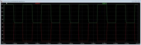
See the pictures of a other circlotorn without feedback, I did set 2 nF on the resistors to earth on the 2.2k resistors, looks it drives well capacitance, I need to compensate, the LTP is wayyyy to fast, the sim here is 100 Khz.
This balanced amp has afcouse as with LPT the same problem, it overshoots very badly, here we have not differential section just the old way of following.
As you see now the square is clean also on the 2.2 K resistors above 2n7000 mosfet zvn do also very good here.
Picture three is without the caps, it overshoots badly and overshoots give bad distortion.
regards
Attachments


Last edited:
Hi Kees
Check this modified schematic ,
Where two electrolitic capacitors are added to bootstrap cascoded LTP and to get more gain from it ,
-R3&R1 have to be divided , now each pair can be 2K2+2K2 , but combination of other values are possible too , capacitors can be in range from 22uF-220uF (50VDC min.),
to supres LTP overshoots you can add RC member in between ZVN drains .
Attachments
Last edited:
- Home
- Amplifiers
- Solid State
- allFET circlotron