VAS current
hi Kees,
Be aware that the input capacitance of the FETs on Compound Pair can be significant, and thus a (relatively) high VAS current should be provided/available. Not sure the 2SC-2240 configuration can provide sufficient current.
Good luck !
hi Kees,
Be aware that the input capacitance of the FETs on Compound Pair can be significant, and thus a (relatively) high VAS current should be provided/available. Not sure the 2SC-2240 configuration can provide sufficient current.
Good luck !
Hi Piersma
I am aware of that, the input capacitance of the irf610 is quite low, but because it is a drainfollower we have millier but the mosfet does just 1 x so that is not a big issue, if afcourse I am right here, miller is a effect from a transistor with gain. using cascode here is not a good idea here.
Replacing the smaller 2sc2240 for something more beafy is afcourse worth
considering.
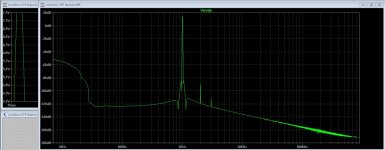
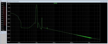
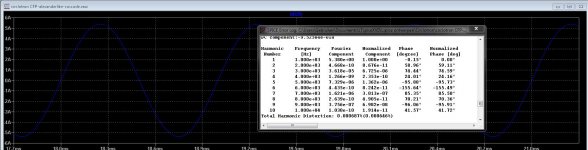
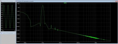
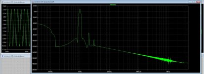
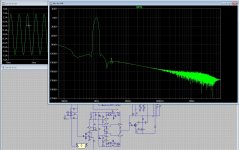
Here I have used a diamond buffer from a old amplifier for current feedback, did need adjustments and such, I have experience with this feedback topology in positive manner. It has a friendly harmonic content. here are the plots of it.
For X it has a friendly respons.
regards
I am aware of that, the input capacitance of the irf610 is quite low, but because it is a drainfollower we have millier but the mosfet does just 1 x so that is not a big issue, if afcourse I am right here, miller is a effect from a transistor with gain. using cascode here is not a good idea here.
Replacing the smaller 2sc2240 for something more beafy is afcourse worth
considering.
Here I have used a diamond buffer from a old amplifier for current feedback, did need adjustments and such, I have experience with this feedback topology in positive manner. It has a friendly harmonic content. here are the plots of it.
For X it has a friendly respons.
regards
Attachments
Last edited:
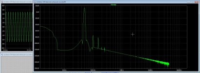
The simulation has a error, is solved now, the output transistors did clip long before the drivers did. cause was a bad model in irf library.
now it is a lot better.
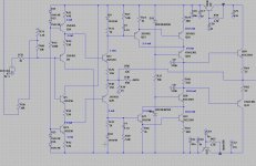
full power alexander current feedback version sim. feedback can also set local.
regards
now it is a lot better.
full power alexander current feedback version sim. feedback can also set local.
regards
Attachments
Last edited:
I have some questions, people here can answer, I am not that good in the caqlculating part or what it does.
I have need a idea to set up the bias, I do this by put a voltage on the input transistors, however it is very sensitive, 20 mV is enough to flipdriver section to one of the rails.
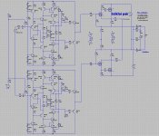
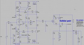
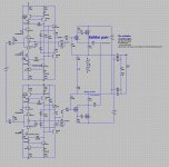
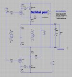
Also two resistors are quite of have influence on the setup, these two resistors are on the driver transistors of the sziklai pairs, R1 100k if I do lower it sensitivity get lower and better, when put the resistor on the outputs of the circlotron it get even better but have then some offset on the outputs who cancel out in fact so not a problem but autobias gets confused.
I let see one half of the amp, R1 is one of these resistors.
I need a idea of setup the idle bias here, it can also be done on the feedback part, but there it is current feedback so it needs adjusted the right way. Because the circlotron is floating and have only ground reference resistors can be make problems?
Idea,s are welcome and thanks in advance.
I did use symetric driver sections because of this does a lot better then half end drivers.
regards
I have need a idea to set up the bias, I do this by put a voltage on the input transistors, however it is very sensitive, 20 mV is enough to flipdriver section to one of the rails.
Also two resistors are quite of have influence on the setup, these two resistors are on the driver transistors of the sziklai pairs, R1 100k if I do lower it sensitivity get lower and better, when put the resistor on the outputs of the circlotron it get even better but have then some offset on the outputs who cancel out in fact so not a problem but autobias gets confused.
I let see one half of the amp, R1 is one of these resistors.
I need a idea of setup the idle bias here, it can also be done on the feedback part, but there it is current feedback so it needs adjusted the right way. Because the circlotron is floating and have only ground reference resistors can be make problems?
Idea,s are welcome and thanks in advance.
I did use symetric driver sections because of this does a lot better then half end drivers.
regards
Attachments
Last edited:
HI,
Just delete R51 on your schematic
to bias mosfet you only need R25 and R26 un this schematic :
Just delete R51 on your schematic
to bias mosfet you only need R25 and R26 un this schematic :
Attachments
Last edited:
Hi Ultimate
Thanks for respons.
I have some other kind of drivers, using balanced drivers the normal way, and it is current feedback, so, now I have done using voltage to the input, or the feedback input for that mather.
I go use a autobias, so need one point of input, to get the circlotron idled I do need some positive volts, like yours also do, when I use a pnp version sziklai I need opposite voltages to get it in idle.
The amplifiers who use this in normal amps do use voltage on the input also.
I only did see that it quite sensitive when approach the middel voltages, 10 mv is already enough to swing big in amps, so i need a divider here.
First what I go do is test the compound in real and make a driver board, these can behave nice with thermal runout troubles. Simulation is not always oke, I have everyday a other outcome, then low, then high distortion., maybe I have setup ltspice wrong.
Current feedback has some more distortion as voltage feedback, but I like the sound more.
Your idea of remove a resistor and use that as idle adjust point does not work, because the driver is from itself already balanced x 2. I just need to put it some out of balance getting a voltage for idle, as the designers did where driver came from.
regards
hi Kees,
Be aware that the input capacitance of the FETs on Compound Pair can be significant, and thus a (relatively) high VAS current should be provided/available. Not sure the 2SC-2240 configuration can provide sufficient current.
Good luck !
Hi Piersma
Maybe you can provide a answer here.
I did testing only the compound stage setting a bias to it.
Complete failure, it oscillates on a very low frequency giving pulses who are very fast, this do start when I start the bias flowing.
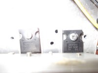
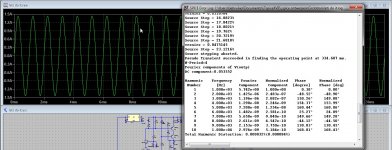
In simulation compound is rock solid stable. I have some idea, I have fake parts.Here some pic,s this is very strange, I get also different bias values, one side is 100 ma then the other side is 120 mA both get same voltage through 1 % resistors, quite possible the irfp240/irf9610 is fake being ibgt,s not first time.
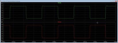
See scope pic, these pulses are big voltage and very small. In sim it does fien see pic, also square signals looks very nice, no overshoot. But I now sim is not always trustable, models need to be fine.
regards
Attachments
I am sooooooooo stupid guy, you will never gess what was wrong, as the saying is the simpler the problem the more complicated the solution.
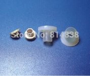
I have forgotten to put washers between the small mosfet and the heatsink causing the drains connecting together. I have search, search and now found (after alcohol was evaporated😀).
The result, it act a little as a lateral I have now put bias on without any correction servo, it pendle bewteen350 and 500 Ma. the driver mosfet needs a own heatsink, together do work as a normal vertical mosfet it will run out of steam.
The bias you see on picture is cold, but after heatsink is 68 degree the bias is 620 mA reason is the small heatsink on the drivers who is working in class a and get hot (use a small heatsink from pc videocard), if you take care of a good cooling of the irf9610 or the irf610 for the other positief version with a pmosfet it will work quite good, just a small extra security can be used, I do that tomorrow, because it is now still 36 degree inside mie house, we have a severe heatwave and have still some days with 35/38 degree to go.
What do I feel stupid today, the compound is rockstable, I was the error..
Wereld kan raar lopen, zo ook de hobbie Piersma.
Attachments

Last edited:
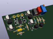
PCB
Great you solved the problem.... (probably a weather related issue)
How is the PCB progressing?
Great you solved the problem.... (probably a weather related issue)
How is the PCB progressing?
The pcb is not yet done.
Busy with the servo, temco needs to get good, the mosfet compound has very low temco, but still need it, looks like I need a special one, so I go look at transistor diode in cascode.
I do set bias by voltage on driver input or feedback to get it to -3.4 volts needed on the output, but ideas are welcome.
What I do see with the front end, it does flip to negative rail on it,s own, is this because of the models are not acting as paired transistors? I thing yes that is the cause, I need to inject 4 volts to get it at zero, I use that also for the bias, but do now find out or there are better ways, injecting on the feedback node do not much, it is low ohm there because that current feedback, maybe injecting a current from a current source will work, or afcourse other places in the circuit, enough places there but distortions need to stay low.
regards
Attachments
Now I am ready programming, I can go on with the amp, seen the corona crisis and much of time now I go start with the pcb and see what the result is.
Everthing is stopped for now,, reason Corona.
Mother and other friends needs help and as such I am busy there.
But I am afcourse ready to start again in new year.
busy now with pcb but also is temporary stopped.
regards
Mother and other friends needs help and as such I am busy there.
But I am afcourse ready to start again in new year.
busy now with pcb but also is temporary stopped.
regards
Attachments
Kees
It is nice to see progress !
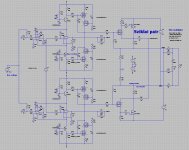
If you remove cascode part and add current mirrors be sure that K170 Vds is not so high ,
yes I see now why those two 680R(1K) resistors have to remain , in between they add some level of bootstrap to driver stage ,
DC offset is usually very small by circlotron OPS , but check for OPS-IQ stability with those power IRP`s ,
btw ,sorry for my off topic but when you want check this allfet concept schematic based on Infinital A-class amp .
best regards !
HI,
What mosfet do you use in this schematic ?
Hi There
Th Circlotron project was stalled, better I was stalled because of Corona, I had to much work helping people and mother who is 90.
But the end is near, and if everyone let them vaccinating the virus can be made gone for ever.
I am now also busy with class D Gan, very promising but this circlotron (with autobias so the IRF does fine) I go make if the PCB cnc is ready, I am building now.
I use the irfp240 mosfet and irf for driving and get lower Nc.
testing stepmotor for cnc, sorry for the singing microstep sound. - YouTube
Testing the Z axle.
testing the spindle 20.000 rpm.
chinese spindle start up. - YouTube
Last edited:

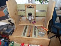
Be back here and go on from here about the circlotron designs. This version is
more simple. For the questions about the pcb, I have not design yet, just keep
following it.
Now I am busy with the pcb cnc build. Nice sound that mircostepping, Sound is a little bit loud
but that is because of the camera little to sensitive ,mic.
more simple. For the questions about the pcb, I have not design yet, just keep
following it.
Now I am busy with the pcb cnc build. Nice sound that mircostepping, Sound is a little bit loud
but that is because of the camera little to sensitive ,mic.
![DSCN5261[1].JPG](/community/data/attachments/1077/1077369-c799f6fd395cade9c75d9345c502708d.jpg?hash=x5n2_Tlcre)
- Home
- Amplifiers
- Solid State
- allFET circlotron