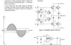
Nice work ! I like the simplicity and the harmonic profile. Looks like SE Class A but low THD.
We should build this one.
Hi X
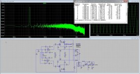
Do now this one has a opamp who can not have more then 24 volts x 2, so the output power is limited, mine idea was a discrete opamp who is maybe more complicated bit not that much, or a extra output stage on higher voltage. Did you see the distortion is -170dB? 1.8 amps out. I did use opa opamps these do nice and sound well.
But and this is maybe a clever idea, using a other kind of output stage who does 2x is a solution, and that can, but maybe bias correction does give trouble.
The other one is a current feedback version but looks a little strange.
regards
Last edited:
Hi kees
I see that you reuse what I proposed in 2019
OPA604 Circlotron | Circlotron Audio
http://circlotron.audio/data/simulation/img/opa_B.png
how do you bias the output stage? with the voltage source on opamp input ?
I see that you reuse what I proposed in 2019
OPA604 Circlotron | Circlotron Audio
http://circlotron.audio/data/simulation/img/opa_B.png
how do you bias the output stage? with the voltage source on opamp input ?
Last edited:
X Hi Yes you had in past proposed that, I did keep that idea alive.
But because you did use a lot of bjt and did make it some complicated and also the loss of the source follower voltage causing the amp less output was a minus, and also little strange setup with a lot of current sources who does not always give stability.
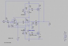
You now I did want a allfet, what I did now is use a compound pair of mosfet output, and I have two ways to feedback also like local with opamps and the output compund has already his own feedback.
I can possible not get a allfet amp without trouble like distrortion because of the gate capacitances, that is a minus for the amp.
If i replace the op604 with a 071 then I have again a allfet😉
The pic head is maybe a nice sounding headphone amp alexanderlike.
That is why I did a alexander cicrlotron, using real current feedback, I say because I have build the alexander in past, with bjt and ring emittors transistors in output, that did sound so well that the people in the high end store where I did test it, yes before I was here on diyaudio was that, the people did look up because al the other amps did not that good job. Did sound very well. I like current feedback and the 604 circlotron is a voltage feedback type.
regards
I have now
But because you did use a lot of bjt and did make it some complicated and also the loss of the source follower voltage causing the amp less output was a minus, and also little strange setup with a lot of current sources who does not always give stability.
You now I did want a allfet, what I did now is use a compound pair of mosfet output, and I have two ways to feedback also like local with opamps and the output compund has already his own feedback.
I can possible not get a allfet amp without trouble like distrortion because of the gate capacitances, that is a minus for the amp.
If i replace the op604 with a 071 then I have again a allfet😉
The pic head is maybe a nice sounding headphone amp alexanderlike.
That is why I did a alexander cicrlotron, using real current feedback, I say because I have build the alexander in past, with bjt and ring emittors transistors in output, that did sound so well that the people in the high end store where I did test it, yes before I was here on diyaudio was that, the people did look up because al the other amps did not that good job. Did sound very well. I like current feedback and the 604 circlotron is a voltage feedback type.
regards
I have now
Attachments
Could you try the bias on input opamp on this schematic ?
i dont have ltspice here
i dont have ltspice here
An externally hosted image should be here but it was not working when we last tested it.
This schematic has source followers, do now you loose the gate source voltage in output voltage?, in a circlotron not that bad but still because of the limited output of the opamps it counts in power output.
Maybe the use of a discrete opamp voltage can be higher then, this will work.
Do you mean normal bias or autobias>?
regards
Maybe the use of a discrete opamp voltage can be higher then, this will work.
Do you mean normal bias or autobias>?
regards
Hi Kees,
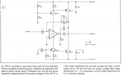
You can boost the voltage capability of any opamp with a bootstrap like this:
Surjan Dogran's Easy Peasy 70v peak-peak Opamp for $1
Or just buy higher voltage opamps. Several are listed in the above referenced thread. A discrete custom opamp is a project in itself. For example:
https://www.analog.com/media/en/technical-documentation/data-sheets/6090fe.pdf
Last edited:
Hi X
I am aware of that, but I like the burr browns very much, so here we need a extra bootstrap indeed, but only if you need more power then 70 watts otherwise the opamp alone is enough, keeping it simple.
I did thought about a discrete opamp, so I can make it for higher voltages, I see different ones on google, using bjt alone for that works the best jfets are disappair in time already.
Thanks for the links, nice readings.
regards
Last edited:
Hi Kees,
You can boost the voltage capability of any opamp with a bootstrap like this:
Surjan Dogran's Easy Peasy 70v peak-peak Opamp for $1
Or just buy higher voltage opamps. Several are listed in the above referenced thread. A discrete custom opamp is a project in itself. For example:
https://www.analog.com/media/en/technical-documentation/data-sheets/6090fe.pdf
The higher voltage opamps are not that good as the 604/626 high grade audio opamps, so we need a high end solution also. these exsists, but have to leave mine allfet idea.

Oke X
This one looks a good one for you, it has voltage feedback and some currentfeedback.
The autobias does his work, see pic 2, it's needed for a vertical fet and sure for a compound.
Whit lower feedback I did reach 200 watts with low distortions
regards
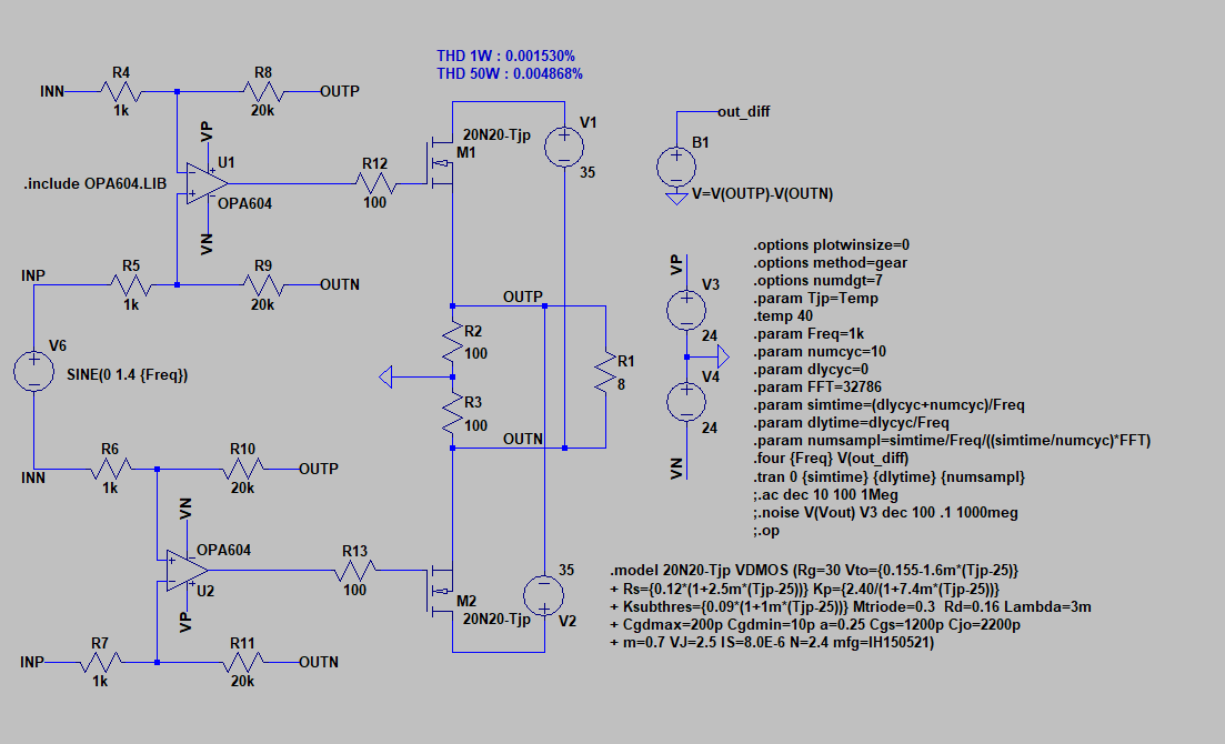
This one looks a good one for you, it has voltage feedback and some currentfeedback.
The autobias does his work, see pic 2, it's needed for a vertical fet and sure for a compound.
Whit lower feedback I did reach 200 watts with low distortions
regards
Attachments

Last edited:
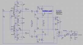
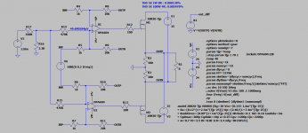
This might work well too. Nice one I think:
It has diodes and is quite the same as previous post.
But I can get with 24 volts max 4.5 amps over 8 ohms dat is quite some power.
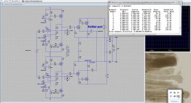
The autobias is now oke, the diodes in the precision rectifier did need reversed, this because it is a little in the negative zone, that is because circlotron needs some volts negative for bias, I did this through the input opamps now driven by the autobias.
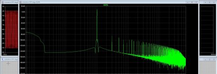
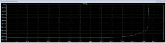
It keeps even with 29 mA distortion below -70 dB with almost full power (4Amps).
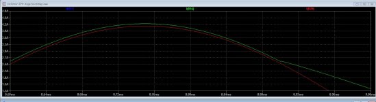
As a result the thermal runaway is gone, see the temperature plot, if it
get real hot it go even to to zero.
harmonic distortion on 4 amps -70dB. On 2 amps it is -120dB or more.
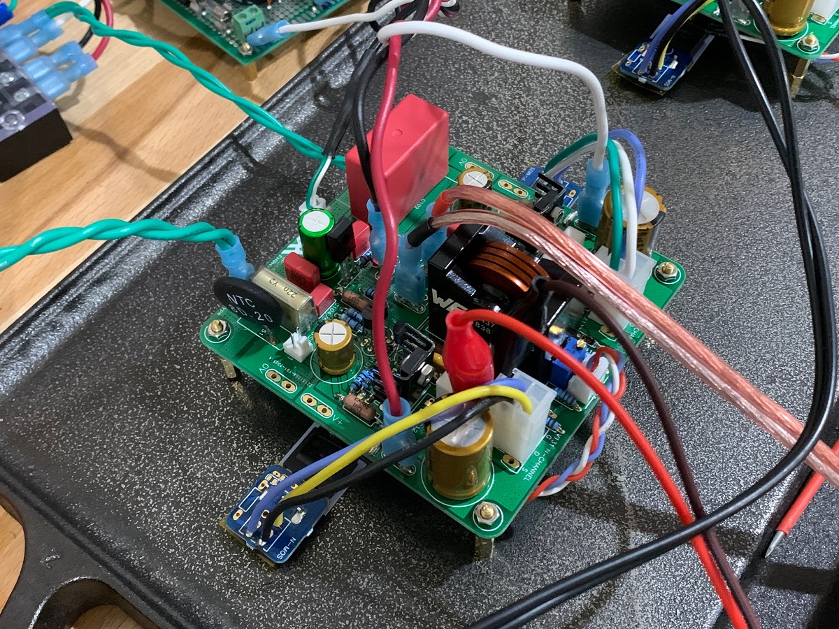
All simulation we need to build
regards
Attachments


What concerns autobias, I did have a schematic from mine old amp who is now a donor for the supply to the hybrid amp.
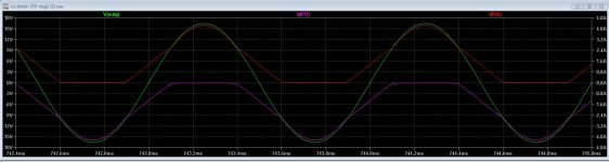
You see also here the effect on signal and current, current follow and stays above signal, this is a variable bias system
not a autobias, that is the other pic.
And now I go to sleep.
regards
You see also here the effect on signal and current, current follow and stays above signal, this is a variable bias system
not a autobias, that is the other pic.
And now I go to sleep.
regards
Attachments
Last edited:
This schematic has source followers, do now you loose the gate source voltage in output voltage?, in a circlotron not that bad but still because of the limited output of the opamps it counts in power output.
Maybe the use of a discrete opamp voltage can be higher then, this will work.
Do you mean normal bias or autobias>?
regards
I mean normal bias on input, I just try it on my schematic, it works !
Attachments
Perhaps use 20 turn 5k trimpot for R16 to allow bias adjust and add 1uF bypass cap above the two 470k resistors.
Perhaps install traces and pads for an optional SMT snubber between G and D of MOSFETs. Perhaps nominal 220pF NP0 and 47R. Populate if we see oscillation issue.
Also, add optional cap in parallel with R8/9/10/11 for silver mica or NP0 circa 15pF to 33pF in case oscillation is an issue.
Always good to have extra optional pads installed when doing layout. Costs nothing but makes modification a snap and looks clean.
Also important to use good non inductive non metal oxide 3W resistors for R2 and R3. Ideally bulk metal KOA BPR or metal thin film.
I would also make the board following latest mechanical outline of all my Class A/AB amps to have optional flying leads on Molex Minifit connectors for the big MOSFETs. It makes removing the PCB for modifications during verification builds a snap. I have found flying leads circa 6in long are not an issue especially if a snubber board is installed on the pins directly to remove mechanical strain and allow snubber to be as close to pins as possible.
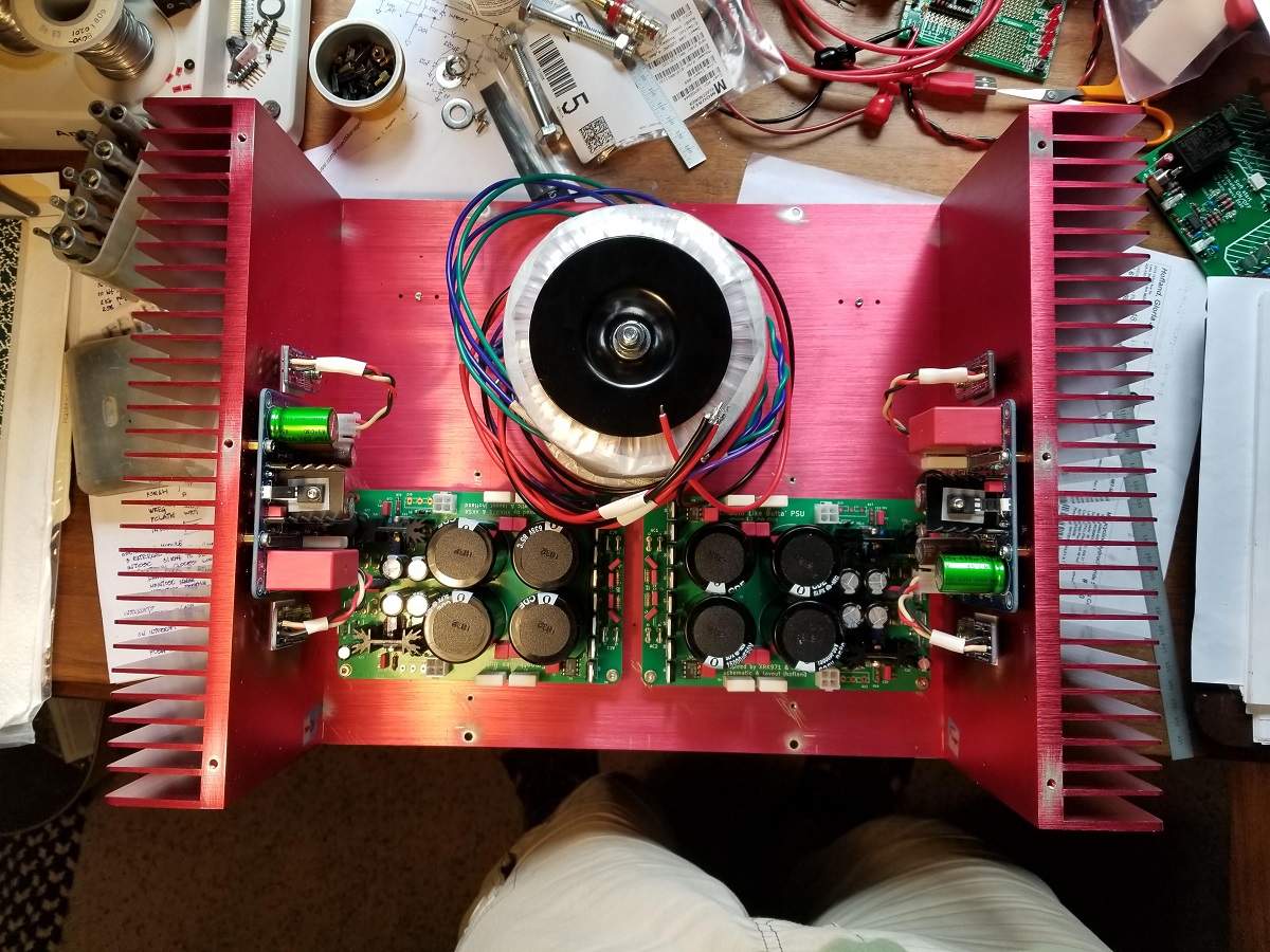
Like this (how Alpha Nirvana or FH9HVX was done)
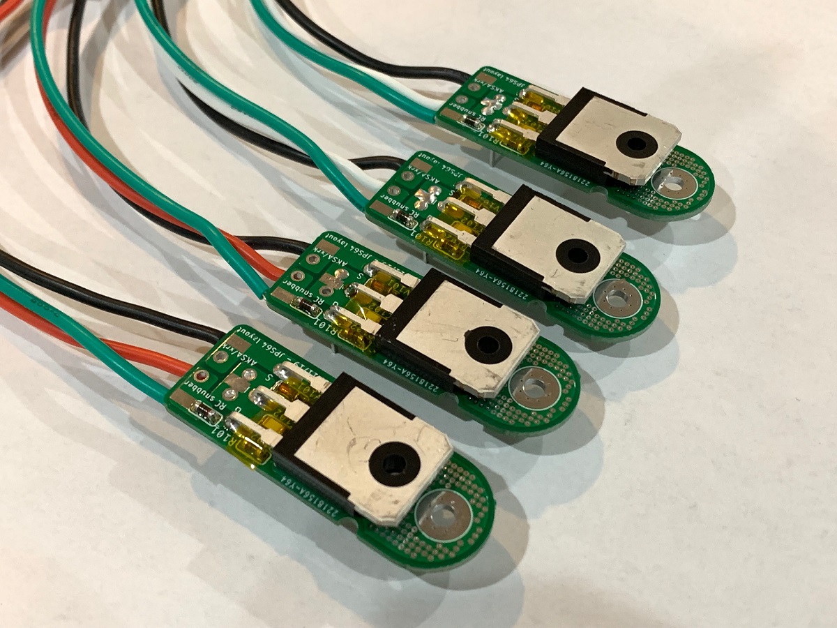
Here is a new Alpha Nirvana build in progress and you can that it allows separation of the amp PCB from the heatsink MOSFET mounting. Thus removal and replacement of the PCB takes minutes.
Perhaps install traces and pads for an optional SMT snubber between G and D of MOSFETs. Perhaps nominal 220pF NP0 and 47R. Populate if we see oscillation issue.
Also, add optional cap in parallel with R8/9/10/11 for silver mica or NP0 circa 15pF to 33pF in case oscillation is an issue.
Always good to have extra optional pads installed when doing layout. Costs nothing but makes modification a snap and looks clean.
Also important to use good non inductive non metal oxide 3W resistors for R2 and R3. Ideally bulk metal KOA BPR or metal thin film.
I would also make the board following latest mechanical outline of all my Class A/AB amps to have optional flying leads on Molex Minifit connectors for the big MOSFETs. It makes removing the PCB for modifications during verification builds a snap. I have found flying leads circa 6in long are not an issue especially if a snubber board is installed on the pins directly to remove mechanical strain and allow snubber to be as close to pins as possible.
Like this (how Alpha Nirvana or FH9HVX was done)
Here is a new Alpha Nirvana build in progress and you can that it allows separation of the amp PCB from the heatsink MOSFET mounting. Thus removal and replacement of the PCB takes minutes.
Last edited:
HI Xkr, you're right, and especially for a prototype, you have to add traces everywhere to add components
for R2 R3 i have used MP915-300-1% in my last amp : DIY mosfet circlotron - YouTube
for R2 R3 i have used MP915-300-1% in my last amp : DIY mosfet circlotron - YouTube
I mean normal bias on input, I just try it on my schematic, it works !
There is a difference Ultimate, you use lateral mosfets, loose 8 volts from the opamps.
I use vertical mosfet in a sompound configuration then we need a other kind of bias, I did use the autobias because it is on a circlotron easy to implement.
Here see them plot with it.
Your lateral version has no need of a servo, but autobias takes care the idle current is always present see the plot, give it extended class A mode. It works
like you did by inject a voltage on the opamp inputs, here a servo opamp does this.
On the autobias pic you see the green output signal always stays above the idle current, who is very good.
regards
Attachments

Last edited:
Maybe we could use lateral mosfet in compound too
what do you use as driver ?
if you want made all vertical fet we could made this :
https://circlotron.audio/sites/default/files/2020-06/nofeedback.png
what do you use as driver ?
if you want made all vertical fet we could made this :
https://circlotron.audio/sites/default/files/2020-06/nofeedback.png
Last edited:
- Home
- Amplifiers
- Solid State
- allFET circlotron