HI Kees,
you should look here, for an all fet circlotron with Hexfet and thermaly stable :
https://www.diyaudio.com/forums/solid-state/261515-vssa-circlotron-15.html#post5792978
What do you think makes the circuit mentioned thermally stable? IRF9520? What is time lag (or constant for the matter) in such an arrangement. It might work if you bring voltages up really slow.
Hi All
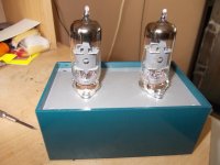
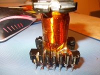
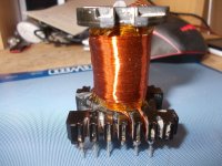
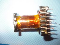
I have start making a voltage amplifier to drive the circlotron with autobias, it is just a test to see what happens, I go drive it with two caps, otherwise I get some voltage, not nice.
tubes are good for getting high voltgage output because I need also to drive it to clip, then I can see what it does with the autobias.
regards
Attachments
What do you think makes the circuit mentioned thermally stable? IRF9520? What is time lag (or constant for the matter) in such an arrangement. It might work if you bring voltages up really slow.
I think that 300 ohms and such big cap, make the circlotron not floating well, starts with uge offset for example, a circlotron needs to be floating well there is also audio signal on the cap to ground, what does that?.
HI
the cap is lowered to 100uf, dont need more
https://circlotron.audio/data/simulation/img/j113.png
this capa is there to get a stable voltage from the floating for the first two stage
the cap is lowered to 100uf, dont need more
https://circlotron.audio/data/simulation/img/j113.png
this capa is there to get a stable voltage from the floating for the first two stage
Last edited:
HI
the cap is lowered to 100uf, dont need more
https://circlotron.audio/data/simulation/img/j113.png
this capa is there to get a stable voltage from the floating for the first two stage
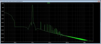
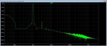
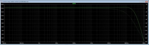
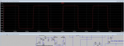
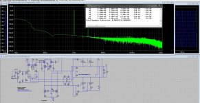
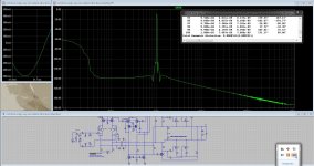
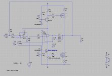
There is still a cap into signal path of the circlotron, and the driving of the mosfets, the vertical ones has quite high nC only the irf460 is lower, and you need a beefy driver for bandwith, that is why I have a extra driver in class A before the verticals, it lowers distortion a lot.
see pics, one with 6.5 amps out in 8 ohms and one with 1.2 amps out on 8 ohms, the autobias works nicely.
last pic is bandwith, oke with a extra driver in class a, but need higher voltage for driver section to get mosfets fully driven.
I now mine is more complicated, but needs are high end.
regards
Attachments
Last edited:
Hi All
I have been not here for a time, reason is a gang to the judge, much work with that and helping someone, I do come back soon.
regards
I have been not here for a time, reason is a gang to the judge, much work with that and helping someone, I do come back soon.
regards
Long time ago but was playing with the amp, and discover possible a big error, who is now corrected, I get now very low distortion figures, and fast respons, just by puuting two resistors in, what also did give a low rest voltage so I can use a autobias.
I was started afain because parts for class d coming not that quick, secial with that corona virus things go slow.
Th distortion is with 1 amp idle current, but halving it to 500 mA did not give much more hd.
regards
I was started afain because parts for class d coming not that quick, secial with that corona virus things go slow.
Th distortion is with 1 amp idle current, but halving it to 500 mA did not give much more hd.
regards
Attachments
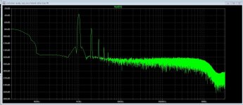
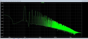
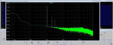
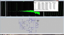
I have a question about distortion in the input stage with the jefet, and the differential vas after.
I get low distortion in the output but see nasty distortion in the vas and input stage, I think the input needs changed, here is that distortion seen.
But maybe somewhone can explane, because unfortanely I do not now everything.
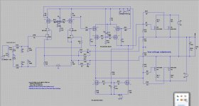
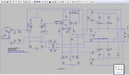
Pic is first input, then vas and output, and schematic.
thanks.
I get low distortion in the output but see nasty distortion in the vas and input stage, I think the input needs changed, here is that distortion seen.
But maybe somewhone can explane, because unfortanely I do not now everything.
Pic is first input, then vas and output, and schematic.
thanks.
Attachments

I've also seen this behavior in amplifiers using global negative feedback.
You could try changing the amount of feedback and seeing what happens. More feedback (making R14-R15 smaller) should make distortion smaller at the output and larger in the earlier stages. Less feedback (making R14-R15 larger) should do the opposite.
If that's what happens, you are just seeing negative feedback at work.
I've also seen this behavior in amplifiers using global negative feedback.
You could try changing the amount of feedback and seeing what happens. More feedback (making R14-R15 smaller) should make distortion smaller at the output and larger in the earlier stages. Less feedback (making R14-R15 larger) should do the opposite.
If that's what happens, you are just seeing negative feedback at work.
I have try that now, here are the results, did need lower it much to get rising distortion output.
Do see not much differences, maybe I do load the input stage to much because it go directly to a drainfollower who is a cascaded one, still it has inputcapacitances who do get nasty sometimes.
Maybe the setup is bad, I do use current feedback and no current source there as result, otherwise it will give trouble.
I go read some more here.
Input Stage Distortion
regards
Attachments

Last edited:
Have you tried removing C9?
If I remove that elco, (do not now why it is there killing local feedback) it is some better in higher frequencies.
I have read some about corrections in long tail pairs, and differential drivers, er are al lot readings about, audio amps special analog everything is already used or patented and free again.
I go dawn a normal amp, see what happens there in sim, and read some more.
file:///C:/Users/Gebruiker/Downloads/Input%20Stage%20Distortion.pdf
Last edited:
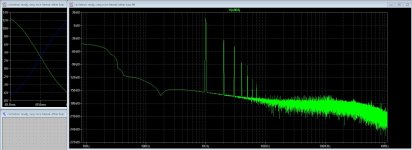
We maybe the error is because of the offset present on each side, this cancel out offset on speaker but does inbalance the differential inputs, special because it is current feedback, I go try a way to cancel out and test.
The new kind of input amp I did use now, it has the same kind, so the feedback in action is really a possibillity, I do not now how much people here did though on that!
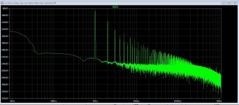
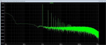
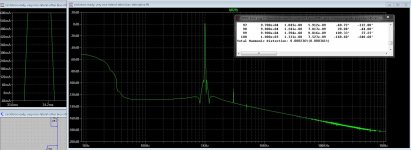
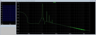
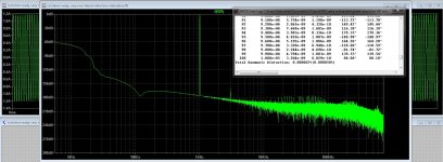
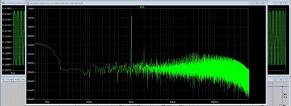
Pics are first is output distortion, second is VAS distortion feedback connected, thirth is output distortion with the new input stage jfet/pnp and fourth is open loop VAS.
We now unbalance in a long tail preamp does go bad. Photo three is with just 120mA idle.
regards
The new kind of input amp I did use now, it has the same kind, so the feedback in action is really a possibillity, I do not now how much people here did though on that!
Pics are first is output distortion, second is VAS distortion feedback connected, thirth is output distortion with the new input stage jfet/pnp and fourth is open loop VAS.
We now unbalance in a long tail preamp does go bad. Photo three is with just 120mA idle.
regards
Attachments
Last edited:
Wel You never gess what was wrong? I say it, the voltage of the preamp circuits need really to be high because of using cascodes, I have rise it to 80 volts x 2 and now things bevavior is much better, we need enough voltages to drive the output mosfets. Because of voltage error I have removed the ltp and put in a cfb circuit who is suitable for current feedback, and it did work.
The lateral version does the best.
Now to the autobias, I need to inject the bias voltage somewhere, like into the lower vas current sources with a opamp or so.
The lateral version does the best.
Now to the autobias, I need to inject the bias voltage somewhere, like into the lower vas current sources with a opamp or so.
Attachments
Last edited:
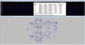
Wel now I have put some sims here, but now i now also disbalans is a big problem, special when using a extra driver fet into the output section who is a source follower does make it unbalanced in driver section, and there comes the trouble from.
using not a extra driver but using a beefy VAS and laterals, I get quite beautifull numbers.
I can post the circuits, for playing with it.
regards
using not a extra driver but using a beefy VAS and laterals, I get quite beautifull numbers.
I can post the circuits, for playing with it.
regards
Attachments

Do not parallel output devices...you will run into troubles !
Why? never had trouble, just use source resistors and sometimes whith laterals a small cap, but that was most with Pfets and these are not used here, th circlotron I had made has verticals paralell, no problem, no oscillations.
regards
For what power I desire, I think it will be on pair, but do the pcb for 2 pair because we do never now, like for bass.
Hi all
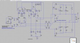
I do post here a alexander circlotron haha, i was again driven by combining stuff.
yet low distortions, I did try with opamps does work fine but some limited output, need discrete here.
X I have use the alexander preamp for driving the pair in the outputstage.
see the pic, For you maybe, using only the prestage can be interesting for the headphone, a true current feedback amp and fast, some adjustments needed.
The very low hd version is a voltagefeedback one with opamps, however discrete opamp is better, more headroom.
regards
Attachments
- Home
- Amplifiers
- Solid State
- allFET circlotron