Hi kees, do you try ZVP2110G for vas ?
I have into mine lib the ZVN4424A\ZVP4424A used in a previous circlotron with X.
here I have found a amp who is N-fet only, this driver with vas can be used for a circlotron. but only low voltages on supply except when be a cascode.
regards
Attachments

cant edit my post 🙁
Code:
*ZETEX ZVP2110G Spice Model v1.0 Last Revised 22/7/04
*
.SUBCKT ZVP2110G 3 4 5
*                D G S
M1 13 20 5 5 Pmod1
RG 4 2 65
RIN 2 5 1E9
RL 3 5 1.2E8
RD 3 13 Rmod1 2.5
C1 2 5 140E-12
**C2 3 2 15E-12
D1 3 5 Dmod1
D2 3 17 Dmod2
Egs1 2 17 2 5 1
Egt1 2 20 5 21 1
Vgt1 5 22 1
Igt1 5 21 1
Rgt 21 22 Rmod2 1
.MODEL Pmod1 PMOS VTO=-2.8 RS=2 IS=1E-15 KP=0.17
+CBD=105E-12 PB=1 LAMBDA=6E-3
.MODEL Dmod1 D IS=5E-12 RS=1
.MODEL Dmod2 D CJO=60e-12 IS=1e-30 N=10
.MODEL Rmod1 RES (TC1=8e-3 TC2=4.2E-5)
.MODEL Rmod2 RES (TC1=-2e-3 TC2=3e-6)
.ENDS ZVP2110Gcant edit my post 🙁
Code:*ZETEX ZVP2110G Spice Model v1.0 Last Revised 22/7/04 * .SUBCKT ZVP2110G 3 4 5 * D G S M1 13 20 5 5 Pmod1 RG 4 2 65 RIN 2 5 1E9 RL 3 5 1.2E8 RD 3 13 Rmod1 2.5 C1 2 5 140E-12 **C2 3 2 15E-12 D1 3 5 Dmod1 D2 3 17 Dmod2 Egs1 2 17 2 5 1 Egt1 2 20 5 21 1 Vgt1 5 22 1 Igt1 5 21 1 Rgt 21 22 Rmod2 1 .MODEL Pmod1 PMOS VTO=-2.8 RS=2 IS=1E-15 KP=0.17 +CBD=105E-12 PB=1 LAMBDA=6E-3 .MODEL Dmod1 D IS=5E-12 RS=1 .MODEL Dmod2 D CJO=60e-12 IS=1e-30 N=10 .MODEL Rmod1 RES (TC1=8e-3 TC2=4.2E-5) .MODEL Rmod2 RES (TC1=-2e-3 TC2=3e-6) .ENDS ZVP2110G
The zvp has a low D S voltage of 100 volts, that is why I did use the 4424A, but in your case it can be used.
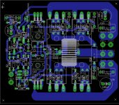
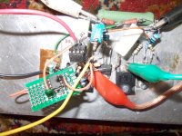
See the pcb of the old version I did with X.
Attachments
And maybe we should use emitter follower between input and vas with IRF9610
what do you think about using emitter follower between input and vas like (C) ?
https://m.eet.com/media/1064165/self_ch18_fig4.jpg
Douglas Self and Bob Cordel use them
I put this page to share the project : Home | Circlotron Audio
what do you think about using emitter follower between input and vas like (C) ?
https://m.eet.com/media/1064165/self_ch18_fig4.jpg
Douglas Self and Bob Cordel use them
I put this page to share the project : Home | Circlotron Audio
If it is not a allfet yes you can do that. a mosfet source follower do lose some volts.
I added two versions to OPA604 with diamond buffer and opa buffer
OPA604 Circlotron | Circlotron Audio
the distortion is almost equivalent to that of a discrete amp O_O
maybe we could replace the OPA604 buffer with a more powerful opa
OPA604 Circlotron | Circlotron Audio
the distortion is almost equivalent to that of a discrete amp O_O
maybe we could replace the OPA604 buffer with a more powerful opa
Last edited:
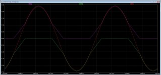
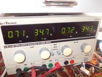
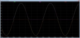
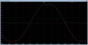
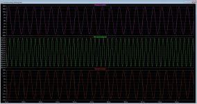
Hio All and Alexberg also, after some time I have started up the autobias again and have now one version tested, this is a misuse of a dc servo who does in a circlotron quite oke, I did have to change the way I did let it work because it did not work with the reference resistors, maybe a wrong feedback but now in dc mode it does fine, 1 amp idle stays 1 amp idle even until the unit is 80 degree hot, it is hot, so the simulation with the straight line is oke then.
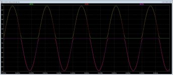
I have a very long rc integrator time, so the initial setup is important to start not to high current for some 2 seconds. Purple and green line is current and the red line is the output signal.
A circlotron does cancel the audio component itselfs, that is why I thought I use a dc servo in a wrong way, not really afcouse but it is connected to the sources of the mosfets, it does tow things keep the dc component low also and watch the current but do not now how it sounds.
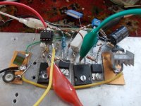
I go build a part for driving, I go use a audio tube.
regards
I have a very long rc integrator time, so the initial setup is important to start not to high current for some 2 seconds. Purple and green line is current and the red line is the output signal.
A circlotron does cancel the audio component itselfs, that is why I thought I use a dc servo in a wrong way, not really afcouse but it is connected to the sources of the mosfets, it does tow things keep the dc component low also and watch the current but do not now how it sounds.
I go build a part for driving, I go use a audio tube.
regards
Attachments
Last edited:
HI kees,
how do you check the frequency stability of your circlotron?
do you check the phase margin ?
thanks
https://www.diyaudio.com/forums/software-tools/101810-spice-simulation-146.html#post5026918
https://www.diyaudio.com/forums/software-tools/101810-spice-simulation-153.html#post5758162
how do you check the frequency stability of your circlotron?
do you check the phase margin ?
thanks
https://www.diyaudio.com/forums/software-tools/101810-spice-simulation-146.html#post5026918
https://www.diyaudio.com/forums/software-tools/101810-spice-simulation-153.html#post5758162
HI kees,
how do you check the frequency stability of your circlotron?
do you check the phase margin ?
thanks
https://www.diyaudio.com/forums/software-tools/101810-spice-simulation-146.html#post5026918
https://www.diyaudio.com/forums/software-tools/101810-spice-simulation-153.html#post5758162
Again, because I have a problem diyaudio site just close suddenly and lost all typework.
I go test the bandwidht and the distortion after the build, a squaretest is also a nice test to get to see the speed and bandwidth, and afcourse to tune overshoot with allfet amps who have capacitances on gate.
simulation give a clue but need real live test.
Now busy with the autobias, it stays perfectly on stable bias point within 0.010 mA between cold and 70 degree chip temp.
I go build a tube voltage amp so I can test, have special for that a high impedance input who is limited by capacitance only.
If I want to check fase margin it is needed more knowledge of LTspice and a different approach because of the balanced behavior.
regards
Last edited:
A circlotron does cancel the audio component itselfs, that is why I thought I use a dc servo in a wrong way, not really afcouse but it is connected to the sources of the mosfets, it does tow things keep the dc component low also and watch the current but do not now how it sounds.
I go build a part for driving, I go use a audio tube.
regards
This is strange. DC bias is a common mode signal, while audio is a differential one.
Use of common mode voltage through LPF or integrator in order to regulate bias will only work in class A. Otherwise it will produce signal proportional to output current thus defeating bias regulation per say.
This is strange. DC bias is a common mode signal, while audio is a differential one.
Use of common mode voltage through LPF or integrator in order to regulate bias will only work in class A. Otherwise it will produce signal proportional to output current thus defeating bias regulation per say.
But I did discover you be right!! when connect the autobias the output signal clips on 3.5 amps, when I disconnect the autobias the clipping is gone, and have 6 amps and lower distortion. You do mean that this is the problem that occur.
I have a extreme stable current when use the integrator, it keeps a levels I set close to 10 mv or such.
The amp does hase some of feedback through the autobias and as such it clips early because it will regulate bias on setup point.
regards
Attachments
Last edited:
Ahh, now I have to reconsider, the limiting of the output signal came from a bad mosfet model, it also did clip without the bias stuff.
As I see it does work, I can clip de amp and still bias remain, if I do include the rectifier circuit you gave me it does not change much, it stays the same.
The servo does measure the voltage over the two 0.22 ohm resistors and that cancels out on the opamp input, left a dc voltage who change with current, that does it now as I see.
defeating bias looks not happen, as I see on the plot. You mean that when I use a not class a regulation like 250 mA this will run out and I get crossover? best to test in real live, I go start make a driver I go use tubes for that, is more easy for testing.
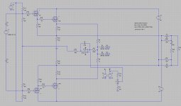
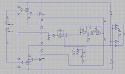
two test schematics one has not the rectifier, but results are the same.
regards
As I see it does work, I can clip de amp and still bias remain, if I do include the rectifier circuit you gave me it does not change much, it stays the same.
The servo does measure the voltage over the two 0.22 ohm resistors and that cancels out on the opamp input, left a dc voltage who change with current, that does it now as I see.
defeating bias looks not happen, as I see on the plot. You mean that when I use a not class a regulation like 250 mA this will run out and I get crossover? best to test in real live, I go start make a driver I go use tubes for that, is more easy for testing.
two test schematics one has not the rectifier, but results are the same.
regards
Attachments
Last edited:
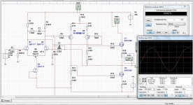
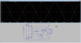
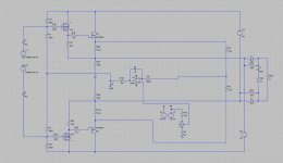
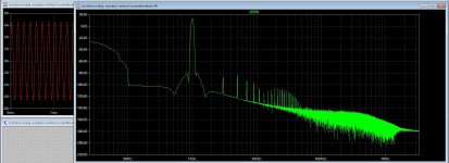
Here I have a complete schematic for simulation.
This has current feedback and a dc servo plus the autobias you did provide.
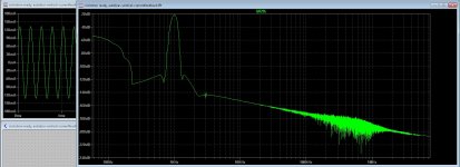
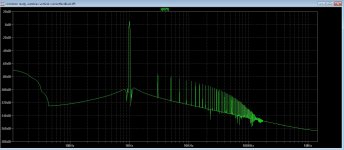
The current is set on 120 mA and with 7 amp output I get -100dB distortion.
Last pic is with 250mA output signal, then I get extreme low hd, and no crossover, it seems that the autobias do work, maybe it is more easy because the circlotron is differential and do cancel signals on input of opamp autobias, this has to do with the use of two resistors from both ends of amp where signals are opposite.
Oke, enough type work, first I go try to get rid of the noro virus, I am not quite happy with my health now and mucho badroom visits.
Post 1052 is not of importance, fault of clip was the model.
This has current feedback and a dc servo plus the autobias you did provide.
The current is set on 120 mA and with 7 amp output I get -100dB distortion.
Last pic is with 250mA output signal, then I get extreme low hd, and no crossover, it seems that the autobias do work, maybe it is more easy because the circlotron is differential and do cancel signals on input of opamp autobias, this has to do with the use of two resistors from both ends of amp where signals are opposite.
Oke, enough type work, first I go try to get rid of the noro virus, I am not quite happy with my health now and mucho badroom visits.
Post 1052 is not of importance, fault of clip was the model.
Attachments


Last edited:
Here I did a temp test, the stuff do work on first eye, the common mode signal is still 500 mV it is not canceled completely,, with the rectifier it is just some mV,s but with the high RC integrator the signal left from the input is very low already. You can see on pic that the canceling happens making a common signal of his own, but I go include the rectifier.
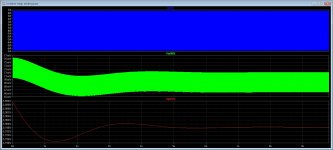
here the test with current and temperature.
Temp stays 500mA low temp and 530mA with high temp,, the bleedresistor on the integrator is cause of a little drift.
YouTube
I go when I feel better build the driver, that way I can see in real live what happens, maybe even interesting.
regards
here the test with current and temperature.
Temp stays 500mA low temp and 530mA with high temp,, the bleedresistor on the integrator is cause of a little drift.
YouTube
I go when I feel better build the driver, that way I can see in real live what happens, maybe even interesting.
regards
Attachments

Last edited:
I can even low pass filtering the signal, and get a low dc voltage with some audio signal left, then let this go into the rectifier and use as dc component, it does work fine. Maybe because it is a circlotron and that is a differential amplifier, connecting two resistors between upper and lower half result in a single common mode signal with some audio rest signals most because of symetry is never ideal. Little confusing is'n it.
Ohh yeh the cap needs to be removed, that does not work. The really solution is or long time sim or building and measure, last is what I do, have ordered a tube supply transformer for this get it over 2 days. tubes are more easy for big signals to test the autobias if it does not runout of steam as you say Alexberg.
Ohh yeh the cap needs to be removed, that does not work. The really solution is or long time sim or building and measure, last is what I do, have ordered a tube supply transformer for this get it over 2 days. tubes are more easy for big signals to test the autobias if it does not runout of steam as you say Alexberg.
Attachments
Last edited:
Alex, to put myself out of misoury without killing myself I have simulate a long time x 2.
You are right all along, it was mine mistake that only two opposite signals was enough to make a simple autobias.
Pic one gives the result of autobias action when driven de amplifier, the second pic let see that after 8 seconds of simulation the amp still draws Idle curent, and pic three let see the result without the rectifier you did mention for me to use, do not work clearly, the integrator just runs out to the rails, happenly the good rail otherwise the amps do blow, and last pic let see what happens when clipping, still draws idle current so this looks very good, I think that the good result is also because of the canceling effect of audio signals in a circlotron when connect both mosfet outputs through 2 resistors, a bridged amplifier is a good candidate for your idea behind this.
so now we now this, I can go on, the result of circlotron canceling is not enough, it does not help I discover now, so this can be closed then and go on.
if the transformer is here I go further with hardware
regards and thanks a lot, without you I did never find that solution.
Attachments
Last edited:
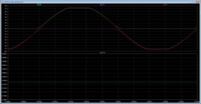
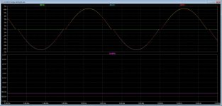
Testing, PIC one with 900mA bias and PIC two with 20mA bias what is extremely low for a vertical.
But as you see the autobias does his work properly still very low distortion with 20mA, it keeps amp from get into class B.
in principle the autobias keeps amp in A? and not in class AB, what means A when low volume and B when play loud where crossover has less impact on quality. That is why I keep lower HD when high volume is present, so it works fine.
regards
Attachments

HI Kees,
you should look here, for an all fet circlotron with Hexfet and thermaly stable :
https://www.diyaudio.com/forums/solid-state/261515-vssa-circlotron-15.html#post5792978
you should look here, for an all fet circlotron with Hexfet and thermaly stable :
https://www.diyaudio.com/forums/solid-state/261515-vssa-circlotron-15.html#post5792978
- Home
- Amplifiers
- Solid State
- allFET circlotron