Wow, you guys are going all out - I wonder where it will end up at and will the pcb be useful for maybe just IRF610 and OPS. Input stage looks like a total redo.
Banat and X
I have measure the distortion of the amp, with a balast resistor and coils, caps, the amp do not mind what you hang on him, it stays stable.
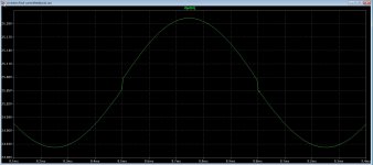
Banat, the cap with the resistor I did have try, but maybe need some more try here, now I have a 1 nF cap from where your bootstrap go to ground, it clean up the overshoots.
Further I do not understand that with such good distortion measurement the amp sound so strange, I have now the idea it is not the LTP but the second one, the 680 ohm resistors do give a low impedance path, but the VAS is in drain follower mode giving high impedance path,.
I go try some things, I go record music and put that on youtube so you can listen.
one is there already.
https://youtu.be/0P8IfKOheto
and the runaway who do now work with a tempsensor.
https://youtu.be/TYHHfgpYx-0
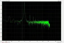
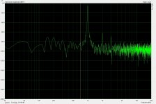
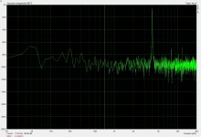
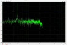
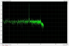
The pictures, the first is measurement of the cd player output, and the rest from amp, from 1 to 10 Khz.
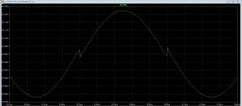
Just judge the outcome, why such low distortion and sounding crossover like.
regards
I have measure the distortion of the amp, with a balast resistor and coils, caps, the amp do not mind what you hang on him, it stays stable.
Banat, the cap with the resistor I did have try, but maybe need some more try here, now I have a 1 nF cap from where your bootstrap go to ground, it clean up the overshoots.
Further I do not understand that with such good distortion measurement the amp sound so strange, I have now the idea it is not the LTP but the second one, the 680 ohm resistors do give a low impedance path, but the VAS is in drain follower mode giving high impedance path,.
I go try some things, I go record music and put that on youtube so you can listen.
one is there already.
https://youtu.be/0P8IfKOheto
and the runaway who do now work with a tempsensor.
https://youtu.be/TYHHfgpYx-0
The pictures, the first is measurement of the cd player output, and the rest from amp, from 1 to 10 Khz.
Just judge the outcome, why such low distortion and sounding crossover like.
regards
Attachments
Wow, you guys are going all out - I wonder where it will end up at and will the pcb be useful for maybe just IRF610 and OPS. Input stage looks like a total redo.
I have not yet decide or things get very different, it looks after all not a problem with the LTP..
And yes X when design a new amp it is possible you did let make the boards for nothing, I need to build a cnc some time, I have the stuff.
regards
Kees,
Thanks for the distortion measurement and videos. Yours sounds much much better than what I heard on mine. With choice of music I could not hear the crossover distortion. If it doesn't show up on measurements it should be fine. What setup is this for LTP?
Thanks for the distortion measurement and videos. Yours sounds much much better than what I heard on mine. With choice of music I could not hear the crossover distortion. If it doesn't show up on measurements it should be fine. What setup is this for LTP?
Kees
One question ,
do you run OPS from that SkyTronic separate power supply box or from your DIY power source ? ,
since Circlotron power bridge need Two Totally Independent and Galvanic Separate power sources , with less as possible capacitive mutual coupling ,
check that SkyTronic power source for those conditions .
Kees
One question ,
do you run OPS from that SkyTronic separate power supply box or from your DIY power source ? ,
since Circlotron power bridge need Two Totally Independent and Galvanic Separate power sources , with less as possible capacitive mutual coupling ,
check that SkyTronic power source for those conditions .
The skytronic is complete separated, I can bridge it how ever but as it is not it works.
I have sim again, there is for shure something with the ltp or the VAS, I can NOT remove the resistor of 680 ohm from vas to ground, I can not adjust it anymore, just jumps from high to low, I can however make it bigger like 2.2k .
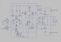
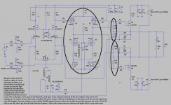
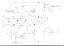
on pictures, LTP, VAS and OTP.
regards
Attachments

Last edited:
I can you all here one thing, thanks to switched off otp will get some ignal through the vas alone to speaker, it did distort heavely, not loud afcourse but it give me the discovery what is the trouble. after setting the idle pot such the voltage get negative in the VAS problem was over, do eat the irf610 something here>,
The VAS when turn the voltage negative, then distortion is gone, also the one side clipping of the driver also dissapears, but only when to negative, I even think then our problem is over, here is the cullprit, I can try remove the lower fets and use two resistors fro try that out, strange behavior but I get closer slowly,.
Anad, the tips have not help unfortanely, but did with the overshoots.
regards
something
X and Anad
What will happen when in the Vas the lower irf610 current source has a higher milliamps setup as the upper irf9610?
You get crossover 😀 because the current source itselfs has to decide who big idle current it needs for vas, I have did this not because I do not alther the source resistors of current source, and when I set it lower as the current source setup it eats away the ilde current for vas, and crossover occurs.
Now I more in trust that we have the fault, but maybe I am wrong, I now when put voltage negative mine suspect is found, because I did drop idle current of irf9610 lower and came under the current source and these did stop eating my bread.
Using resistors to ground do remove also the nasty crossover, because now the current source can not eat my bread anymore. See picture, but adjust idle current is very sensitive but I think this is because of the irfp240 mosfet who have a very low on state.
regards
Attachments
I did test with a headphone on drivers alone, it,s crossover did dissapair when the voltages on the drains did go below 0 volts and negative, however idle
Hmm when disconnect the two 680 ohm resistors from the output and to ground wil also let distortion drops a lot, or remove them completely is possible.
I go now test again,
we get less parts on the way.
regards
Hmm when disconnect the two 680 ohm resistors from the output and to ground wil also let distortion drops a lot, or remove them completely is possible.
I go now test again,
we get less parts on the way.
regards
Attachments
Kees
I like your method by listening output signal from driver stage via headphones 🙂 ,
however headphones need to be connected between U2&U3 drains , right ?
- those two 680R res. have no function except to unnecessarily load the drivers ,
anyway IRFP`s gate`s charge/discharge loops goes via those two 220R ground reference resistors
- if you measure any balanced output signals special by output signal from OPS they need always to be measured in-between of two phase , not only from one phase to the ground line ,
but if you decide to made driver stage to run in A-class than you can measure each driver phase output referenced to ground line ,
and yes running driver stage(or second VAS stage) in A class is good solution .
So are you saying we need to keep the drivers biased and operating in class A by keeping the drain negative? Why does 680R impact that?
My J310's arrived. They look remarkably "genuine" despite from China and out of production. I will wait until you settle on circuit and show it works before changing or working on circuit again though.
My J310's arrived. They look remarkably "genuine" despite from China and out of production. I will wait until you settle on circuit and show it works before changing or working on circuit again though.
Kees
I like your method by listening output signal from driver stage via headphones 🙂 ,
however headphones need to be connected between U2&U3 drains , right ?
- those two 680R res. have no function except to unnecessarily load the drivers ,
anyway IRFP`s gate`s charge/discharge loops goes via those two 220R ground reference resistors
- if you measure any balanced output signals special by output signal from OPS they need always to be measured in-between of two phase , not only from one phase to the ground line ,
but if you decide to made driver stage to run in A-class than you can measure each driver phase output referenced to ground line ,
and yes running driver stage(or second VAS stage) in A class is good solution .
I have did that between the drains afcourse, high ohmic headphone, and also there it sounds good, however, read on.
I have change the concept to get more clean sound and get rid of the crossover, however it did make worse, amp is not friendly to listen to, it is quite hars, mucho to hars.
The two resistors I have removed, but amp driver section is quite unstable, jumps from one to other side of supply giving suddenly a blowup of the fuse.
If I remove that resistor the current feedback can not be used anymore from output, amp is total unstable, no solution here, when connected to gates as local it works, but amp is such hars that I did give uop quick.
What I also did discover, the amp seems mucho friendly if I do setup the voltages on the gates of the irf240 negative, I can see that on the sims, I get mucho distortion of 2, 3 ,4 ,5 harmonics on 10 khz who are almost as strong as 1 Khz, just - 20 db or less.
I can setup the output transistors as drain followers, then it has to be negative but amp has less damping, but more friendly respons.
I can cot find out why this happens, a single ended driver section with a balanced circlotron can be the problem, and so we need to go balanced.
regards
Hehehehe I did screem to early, I have found it in a cery strange corner.
The feedback loop is the cause, it modulates the LTP giving a very strange action.
So now I go make a recording as it is now.
X the amp correct also without a temp sensor, the two lower current source however do overcompansate a little so need of a thermistor of very low value is needed.
be continued just another day.
regards
Last edited:
Hehehehe I did screem to early, I have found it in a cery strange corner.
The feedback loop is the cause, it modulates the LTP giving a very strange action.
So now I go make a recording as it is now.
X the amp correct also without a temp sensor, the two lower current source however do overcompansate a little so need of a thermistor of very low value is needed.
be continued just another day.
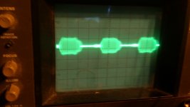
And there are oscillations on the music signal on scope, good sign, because this means it do well, and need compensation.
regards
hehe did make a mistake with previous post.
Ever seen a judge dry? here you see it because of this such beautifull song, just listen to end.
https://www.youtube.com/watch?v=4tEJDxl7uxo
tekst in english, it is about the mother who died, strong girl.
Dat ik je mis songtexten + Engels vertaling (Versie #1)
I was sure the feedback, I did get on the resisistors the signal back who was quite strong as it is in opossite fase it did make trouble.
I listen now, and yes it is now what we need, but as it is transistor the tubes do not be beaten.
But the amp is lighting fast, do you like bass this amp is it.
regards
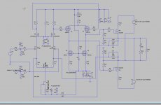
I have now the lowest possible distortion, I idle the 2sk170 on 8 mA and remove one Jfet from the CCS.
What also can be good is a current mirror on top of the LTP and remove the lower Jfet and use a resistor there, A current mirror can also be used such we have low impedance.
for later first this correntions who did give lowest distortion.
Anad, the two resistors of 680 ohm is really needed if I want to use the feedback on output, but also to get things stable, I have use now 1K and this do best, without the amp do run forth and back all the time in current.
However the offset is supriseling good, it stay where it suppose to be but we need to use good 10 turns pot and metal film resistors.
regards
Attachments
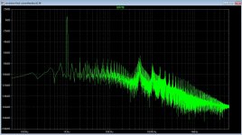
-80dB HD is nice. Good work - Let's see if it holds up in practice. Thanks for working this. Are we able to apply these mods to current PCB?
Kees
It is nice to see progress !
If you remove cascode part and add current mirrors be sure that K170 Vds is not so high ,
yes I see now why those two 680R(1K) resistors have to remain , in between they add some level of bootstrap to driver stage ,
DC offset is usually very small by circlotron OPS , but check for OPS-IQ stability with those power IRP`s ,
btw ,sorry for my off topic but when you want check this allfet concept schematic based on Infinital A-class amp .
best regards !
Attachments
-80dB HD is nice. Good work - Let's see if it holds up in practice. Thanks for working this. Are we able to apply these mods to current PCB?
Now X we have to do the practice of that sim.
We can be use the normal board, and I get to tell you that the two resistors 680 ohm who load the VAS NEED to be in to get stable working, this VAS needs a real load and not a mosfet gate who is capacitive, so I have put them back and are now 1K .
If you do now change it all and test, and hee the idle current is quite stable, but do not go above 500 milliamps, above we need compensation, but this is not the real isseu now sound quality is.
I have another circlotron balanced and without feedback, see if this do work but now I go rest, need to charged because it is continu thinking, thinking.
X I think that the irfp240's sound not as good as the lateral 2sk1058, but this is just my thoughts because I have test them in the hybrid and had there also the grainy sound of them, but maybe also it is the case how better the amp the better you hear bad recordings.
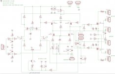
here some pictures and the correntions in the same board, when you have done this you have to make it works otherwise you have something wrong, use all the parts as in schematic, nothing else, the CCS you need to remove one Jfet and change that for theDN2540 small one, or try a PN4391.
succes and let me now when it works, in stereo because I have mono.
The crossover is gone, it was due to the feedback, it needs really current and the resistor to the ccs small, therefore we need bigger fet there or maybe still an bjt with a led because of temp trouble.
mine amp stays without any sensor transistor quite stable on 0.5 amps, it do not move at all, so the irf610 CCS do provide temp compansation aht sim did proof by the way. Maybe other mosfet there we can find one who do well, but is later care.
For as now, I listen to it and get now tired with it, I needs soms slowdown because the slew rate is incredible high and can also be a cause of the grainy sound whe had, but also later care.
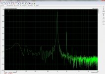
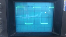
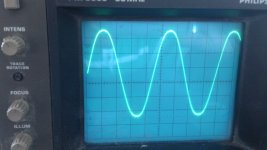
Square wave is 20 Khz, and the measurement HD is with arta, as you see very close to LTspice

The sinus has oscillations on the tops, but that was because of the PC I had measure the HD also with one fase because the other way did short the amplifer.
It is a beast what concers abuse, it can not be broken, short here, drop there he don't care, I can with the supply on the circlotron just disconnect one driver supply and no speaker lancing, I can put supply on driver section with circlotron on without a plop etc.
regards
Attachments
Last edited:
- Home
- Amplifiers
- Solid State
- allFET circlotron