Banat,
That's a nice SET/SEPP quasi amp - could this be done with JFETs on input? Reminds me of my Pass M2 except that's not SEPP but complimentary PP.
Is this a good rig for testing FETs MOSFETs etc due to isolation via transformer?
That's a nice SET/SEPP quasi amp - could this be done with JFETs on input? Reminds me of my Pass M2 except that's not SEPP but complimentary PP.
Is this a good rig for testing FETs MOSFETs etc due to isolation via transformer?
X
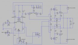
but why to use any JFET`s on input? , since there`s around so many very good sounding and available cheap tubes for one simple and very good sounding A-class SET stage ,
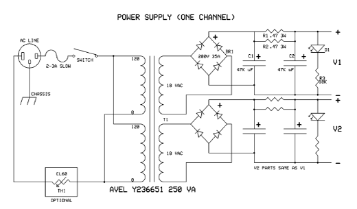
yes this interstage transformer make complete DC isolation from SEPP stage , it is step down transformer , not step-up , with relative low impedance of secondary coils ,and there`s also third secondary for connecting some reference headphones or some high efficiency LS ,
http://www.diyaudio.com/forums/pass-labs/290992-hybrid-class-retro-amp.html
but why to use any JFET`s on input? , since there`s around so many very good sounding and available cheap tubes for one simple and very good sounding A-class SET stage ,
yes this interstage transformer make complete DC isolation from SEPP stage , it is step down transformer , not step-up , with relative low impedance of secondary coils ,and there`s also third secondary for connecting some reference headphones or some high efficiency LS ,
http://www.diyaudio.com/forums/pass-labs/290992-hybrid-class-retro-amp.html
Last edited:
Transformer coupling adds 3rd order harmonic distortion I think. That was my experience with the Pass M2 which is quite nice but not as clear as my usual amps. I haven't used tubes before - just need to get over it and try one of these days.
X
by these specific hybrid amp app. second harmonic will be dominant , generated both from SET stage and SEPP(quasi)stage .
by these specific hybrid amp app. second harmonic will be dominant , generated both from SET stage and SEPP(quasi)stage .
Hi all
Anad now I remember it we have one relative in brajkovac and from there we did need to follow a road who did rise in the air, somewhere half of the 80 km we see small houses as these are so down and we so high, if we follow another 40 km we get in a small village who has a cafe' on entré the bus did als driver to there from belgrade.
that small vollage has a river who is violent in winter, we have to go trough the bedding to get to the other familie who live there, in summer it is 40 + there.
For the amp, your set has a singel supply nothing there to go negative,.
regards
regards
Oke
I have sim now after the dentist did a root canal who however was painless.
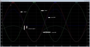
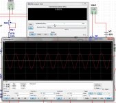
The amp I have go negative, as I see good when the circlotron do 500 mA at +3.8 volts gate voltage what happens as we drive the amp and the sinusoidal signal go negative for some volts when drive it some harder.?
I think on that point it has no idle left? see the pictures. Maybe I miss something here, can I drive a circlotron negative? because it is two singe ended amps in balans.
So we need a
I have sim now after the dentist did a root canal who however was painless.
The amp I have go negative, as I see good when the circlotron do 500 mA at +3.8 volts gate voltage what happens as we drive the amp and the sinusoidal signal go negative for some volts when drive it some harder.?
I think on that point it has no idle left? see the pictures. Maybe I miss something here, can I drive a circlotron negative? because it is two singe ended amps in balans.
So we need a
Attachments

sound of the corrected amp.
https://youtu.be/4t8IkQp18lc
Has a circlotron a swing between plus and minus? because speaker is between minus voltages, it is a little confusing.
Anad I do not see crossover on the scope.
the little cracking you hear is the mobile phone.
for me is sound not bad at all.
https://youtu.be/4t8IkQp18lc
Has a circlotron a swing between plus and minus? because speaker is between minus voltages, it is a little confusing.
Anad I do not see crossover on the scope.
the little cracking you hear is the mobile phone.
for me is sound not bad at all.
Hi all
Anad now I remember it we have one relative in brajkovac and from there we did need to follow a road who did rise in the air, somewhere half of the 80 km we see small houses as these are so down and we so high, if we follow another 40 km we get in a small village who has a cafe' on entré the bus did als driver to there from belgrade.
that small vollage has a river who is violent in winter, we have to go trough the bedding to get to the other familie who live there, in summer it is 40 + there.
For the amp, your set has a singel supply nothing there to go negative,.
regards
regards
Kees
You are free and welcome anytime here in Serbia if you wish to visit those lovely people to you ,
that simple amp SEPP-OPS can run OK just like that with that unipolar PSU ,same as any other quasi amp unipolar supplied .
Kees
You are free and welcome anytime here in Serbia if you wish to visit those lovely people to you ,
that simple amp SEPP-OPS can run OK just like that with that unipolar PSU ,same as any other quasi amp unipolar supplied .
Anad
Thanks for inviting.
I try afcouse make a own amp from scratch.
And I learn of it also, wel after some simulation, it seems that the voltage from the drivers go negative some volts, and this go to the circlotron amp, what happens then is the sinusoidal signal get distorted on one side, because it pass then o amps, the other side go up and have no problems, this also is a fect with the other designs, we need to remove the negative voltages, only some 15 volts negative resides for the LTP.
if I idle the circlotron to 500 mA it still distorts whe I idle aboe 1 amp it stays above the o amp border, leaving a minimum of 200 mA left still to low.
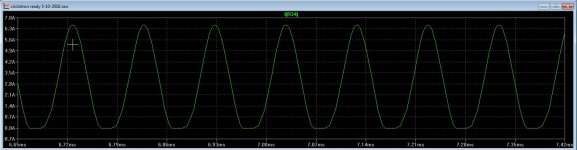
see the pictures where I did low idle giving the flatten bottom tops of the sinusoidal and with 1 amp giving a better signal.
When I do set amp on low volume tthen it is not that problem.
We need a higher Plus voltage and a lower min voltage, when we change the mosfet circlotron to drian follower things are reversed, so we did pinpoint the problems I hope.
This is also why tha amp sound hars as we play loud, and very good if I do play low I did discover, so the sound of the youtube movie is low volume and sound not bad, but still some hars.
X we need to go singe supply, circlotron may never get to negative.
Attachments
Oke
I have sim now after the dentist did a root canal who however was painless.
The amp I have go negative, as I see good when the circlotron do 500 mA at +3.8 volts gate voltage what happens as we drive the amp and the sinusoidal signal go negative for some volts when drive it some harder.?
I think on that point it has no idle left? see the pictures. Maybe I miss something here, can I drive a circlotron negative? because it is two singe ended amps in balans.
So we need a
Circlotron is PP amp , so how much deep can swing each side of that balanced bridge directly depends from setup of idle currents (IQ),
but on your graphs also I can see some net asymetry in the output signal caused from SE- nature of input signal on LTP ,where output signal consist from dominant second harmonic and with third harmonic supresed , I think that you should try to feed that amp with some fully balanced signal to ,
and yes I like very much that relaxed and detailed sound from your amp and from those Philips loudspeaker , I think that now you are very close to full success 🙂
Kees,
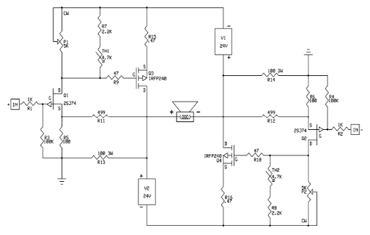
I think you are right, the Circlotron on Pass DIY has single rail supplies... (their schematic is drawn showing P-channel on IRFP240 where it is actually N-channel as arrow should point in.), but SJ74 is P-channel JFET. I set up my PSU the same way - two independent 18vAC secondaries generating 25v. +ve and -ve is 0v both A and B supplies. So the -A and -B were in fact 0V but not connected to each other or ground. You will notice here, again that Pass drives an IRFP240 gate directly with a 2SJ74 JFET.
Furthermore, the article says it needs to run in class A otherwise there will be XO distortion and to do this requires minimum 1.2amps bias.
https://www.passdiy.com/gallery/amplifiers/build-the-amazing-fet-circlotron
PS for one channel:
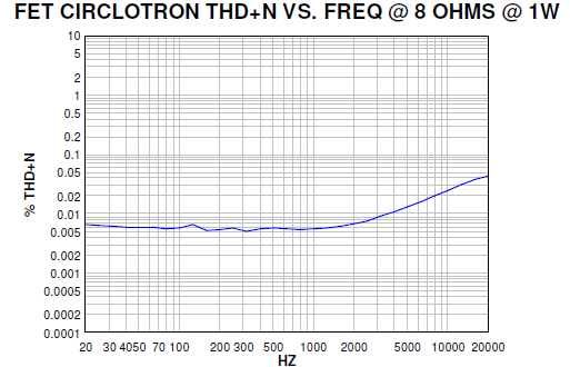
1W into 8ohms:
I think you are right, the Circlotron on Pass DIY has single rail supplies... (their schematic is drawn showing P-channel on IRFP240 where it is actually N-channel as arrow should point in.), but SJ74 is P-channel JFET. I set up my PSU the same way - two independent 18vAC secondaries generating 25v. +ve and -ve is 0v both A and B supplies. So the -A and -B were in fact 0V but not connected to each other or ground. You will notice here, again that Pass drives an IRFP240 gate directly with a 2SJ74 JFET.
Furthermore, the article says it needs to run in class A otherwise there will be XO distortion and to do this requires minimum 1.2amps bias.
https://www.passdiy.com/gallery/amplifiers/build-the-amazing-fet-circlotron
PS for one channel:
1W into 8ohms:
Last edited:
Circlotron is PP amp , so how much deep can swing each side of that balanced bridge directly depends from setup of idle currents (IQ),
but on your graphs also I can see some net asymetry in the output signal caused from SE- nature of input signal on LTP ,where output signal consist from dominant second harmonic and with third harmonic supresed , I think that you should try to feed that amp with some fully balanced signal to ,
and yes I like very much that relaxed and detailed sound from your amp and from those Philips loudspeaker , I think that now you are very close to full success 🙂
Hi X and anad
I did measure wrong, did it on the supply side and that was a clip because of to low idle.
The sound of the amp is better and I think with a lateral mosfet even better.
That phillips speaker is from 1976 so a very old one but unbeatable sound.
Still I like the hybrid better, tubes with mosfets, however the allfet is quite fast making the sound have a nice kick
X
The pass amp has the drivers and input on the circlotron itselfs, and as such need to bias high, I have a symetrical supply so we can also setup A/B I did measure wrong in previous post did measure on the supply resistor and then you see strange signals as idle is low, then it looks like clip what is not the case.
I have to say the amp has to perform wel because the distortion I did measure was very low, -80 dB.
The pass amps has low distortion but that is 1 watt, here I did use almost full power sims.
That amplifier was contributed to the site by another DIYer.
The design would not properly be called a Pass amp, which is not to
say that it's not a fine amplifier.

The design would not properly be called a Pass amp, which is not to
say that it's not a fine amplifier.
That amplifier was contributed to the site by another DIYer.
The design would not properly be called a Pass amp, which is not to
say that it's not a fine amplifier.
I gess you mean previous pass labs posts, mine design is not a pass amp also, I did have mention the charge//discharge a irfp240 mosfet with a 2sj74 is not the best way as I did read it needs a class A driver for it, even current to 800 mA for one set mosfets driven properly. But if I have to believe the author it give a very nice square who did give me doubts, strange electronic world we live in.
X
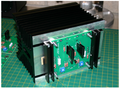
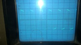
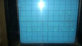
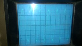
I have measure some things because of tooth pain so so I have some things to set mine mind on and forget the pain.
I have measure in 4 ohms, 2 x 35 volts driver voltage and 2 x 35 volts circlotron voltage.
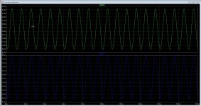
Photo 1 = 20 mV
Photo 2 = 35 volts
photo 3 = clipping ( and smoking ballast resistor😱
On no parts I did see crossover distortions.
Still, I go now try lateral mosfets, current mirror in the LTP.
regards
Attachments
This mosfet is possible a better candidate because it is a mosfet who has a on resistance of 0.27 ohm, for liniair use we need mosfets who has a on resistance of plus minus 0.47 ohm, then we have a much better respons because we can not go to 0 amps again, this happens because the on resistance of the irfp240 is 0.01 ohm and as such clip to the supply very easely and has hard clip, that is bad for speakers.
http://www.vishay.com/docs/91237/91237.pdf
http://www.vishay.com/docs/91237/91237.pdf
Check also IRFP340
It is with R-ON=0,55ohm and is with much lower inter-electrode capacitances than IRFP460 .
It is with R-ON=0,55ohm and is with much lower inter-electrode capacitances than IRFP460 .
Check also IRFP340
It is with R-ON=0,55ohm and is with much lower inter-electrode capacitances than IRFP460 .
This is interesting mosfet but needs two paralelled for class A or more power.
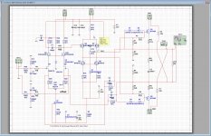
X it can be used indeed, I have used 0.22 in mine and have correct schematic for it, further the biaspot is removed and the CCS is now the idle adjust place, it do much better and I can set the drivers in pure class a with 60 mA each.
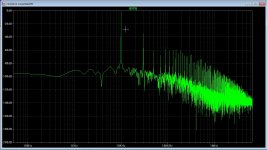
Still some confusion about the signal output who clip to supply in cirlcotron, this happens because the drivers get some volts negative and I do not now what is impact because of crossover, we had, in the new setup I have 80 dB or more HD suppression special the even harmonics the oneven are less supressed and is because the circlotro is a balanced output amp cancels out the even harmonic, that is why people like single ended amps and has Pass Labs also a single ended amp with on one side a high power current source,
uneven harmonics make amp less smooth sounding but afcouse it is all taste for different ears.
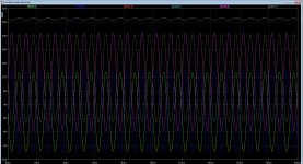
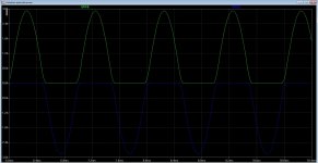
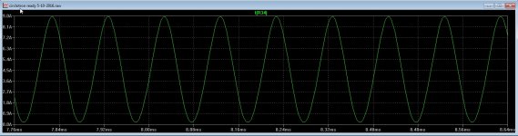
On picture two you can see that the output clips to the supply because of low idle current of 250 mA. picture one is idle current of 2 amps in sim, thirth
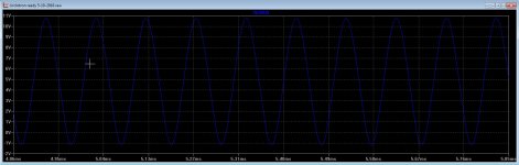
photo you can see the drivers get negative in lower part, who take the circlotron also negative, and I do not now id this has impact on the crossover, I can not measure crossover whith the scope, so it has to be fine and only in sim it is confusing.
first picture we have low distortion. and the two last pictures is how it performs after set drivers in real class A , this means the lower two irf610 do dissipate 2 watts and the above do 1.6 watts but it is way within specs.
Attachments
-
 ScreenHunter_ Oct. 05 15.20.jpg215.2 KB · Views: 122
 -
 ScreenHunter_ Oct. 05 15.56.jpg142.9 KB · Views: 99
 -
 ScreenHunter_ Oct. 05 15.57.jpg138 KB · Views: 91
 -
 ScreenHunter_ Oct. 05 15.58.jpg149.7 KB · Views: 94
 -
 ScreenHunter_ Oct. 05 15.59.jpg144.7 KB · Views: 99
 -
 ScreenHunter_ Oct. 05 13.48.jpg197.1 KB · Views: 100
 -
 ScreenHunter_ Oct. 05 16.22.jpg695 KB · Views: 179
Last edited:
The first picture shows -40dB HD at H2 - that's kind of high isn't it?
Is this the correct DN2540 I need to get then?
DN2540N5-G Microchip Technology | Discrete Semiconductor Products | DigiKey
I guess you have been playing with a lot of options Kees. At this point, do you have a recommendation for salvaging the current PCB into a working Circlotron amp? Please post schematic of what you think is best option at this point for salvaging current PCB. Or are we giving up and moving on to Gen 2 design?
Last edited:
- Home
- Amplifiers
- Solid State
- allFET circlotron