allFET Circlotron First Sound for X
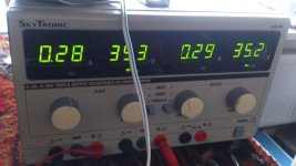
I went in stages as you suggested. Using resistor as current source. I tested the output and saw that I could adjust first get 5mA in each leg of the LTP. Then I installed the drivers and saw that I could adjust the amplitude (bias) and offset on the outputs of the IRF610/9610 via the trimpots from nice range. The I added the IRFP240's and proceeded to operate with 10R safety resistors. Bias current adjustable from zero to huge several amps, and offset was tricky (single turn pot) but stable within 10mV. I set bias for solid pure class A region of 1.3amps similar to Pass amps. Connected the speaker, DAC on input and it's now singing.
I liked what I heard and proceeded to remove the safety resistors and upon power up, the 3A fuses blew. Thinking it was inrush transient I changed to 6A fuses and it still blew. At which point I replaced safety resistors and see that circuit is sorted as it was drawing 20V across the 10R. I probed the IRFP240's and they are blown - reading of 10R to 0R - shorted. These are the first IRFP240's I have ever killed. It's got to be thermal runaway.
I replaced the MOSFETs and am running with safety resistors as current limiters. Playing music at least. I guess we need to find a way to put a current limiter - maybe the Pass opto-coupler and resistor network for current sensing? I don't think thermal feedback will work, it needs to sense the current and limit that because the thermal runaway happened in maybe 2 seconds before the fuse blew.
Here is the setup showing 1.3 amps across the 10R resistor:
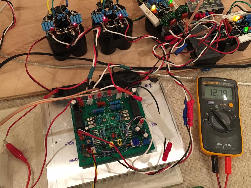
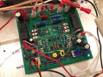
Closeup:

I went in stages as you suggested. Using resistor as current source. I tested the output and saw that I could adjust first get 5mA in each leg of the LTP. Then I installed the drivers and saw that I could adjust the amplitude (bias) and offset on the outputs of the IRF610/9610 via the trimpots from nice range. The I added the IRFP240's and proceeded to operate with 10R safety resistors. Bias current adjustable from zero to huge several amps, and offset was tricky (single turn pot) but stable within 10mV. I set bias for solid pure class A region of 1.3amps similar to Pass amps. Connected the speaker, DAC on input and it's now singing.
I liked what I heard and proceeded to remove the safety resistors and upon power up, the 3A fuses blew. Thinking it was inrush transient I changed to 6A fuses and it still blew. At which point I replaced safety resistors and see that circuit is sorted as it was drawing 20V across the 10R. I probed the IRFP240's and they are blown - reading of 10R to 0R - shorted. These are the first IRFP240's I have ever killed. It's got to be thermal runaway.
I replaced the MOSFETs and am running with safety resistors as current limiters. Playing music at least. I guess we need to find a way to put a current limiter - maybe the Pass opto-coupler and resistor network for current sensing? I don't think thermal feedback will work, it needs to sense the current and limit that because the thermal runaway happened in maybe 2 seconds before the fuse blew.
Here is the setup showing 1.3 amps across the 10R resistor:
Closeup:
Attachments

Nice to see your creation up and running.
Under what load conditions did you test the amp?
I did test the amp with 4.7 ohm resistor.
The square overshoots you see it from the generator, this has a little amp who does that. It is very fast if the amp let it through unharmed doe you think not.
I have no caps in the amp for stability, it is just stable, no oscillations whatso ever, even with input open it do not give trouble.
I go test with the diodes, I did see I need when warming up have to use lower resistance, if you make the 10 ohm smaller the idle current drops, therefore a NTC cab be used, on top of driver things are reversed, when smaller resistance the idle current get higher, so need the PTC, this for clearance.
The bottom is so a nice place however does a diode get lower when warmed? if not it can not be used.
regards
That is sad, you did blew the mosfets, yes thermal runaway is very bad, special because you did put it on 3 amps, do you have good thermal kontact heatsink with mosfets?
I have a supply who can be limited I have put it on 0.5 amps so it can never blow.
It is not bad the sim ehh, so close it was.
Did you also try fiull feedback? by using the middel and outside pins. The new board is complete adjusted now.
regards
I have a supply who can be limited I have put it on 0.5 amps so it can never blow.
It is not bad the sim ehh, so close it was.
Did you also try fiull feedback? by using the middel and outside pins. The new board is complete adjusted now.
regards
The MOSFETs are not expensive so not a big deal. More of a pain to replace them that's all. I have feedback connected with red and blue wire like the diagram you posted earlier. I don't know if that is called full feedback?
I am using silicone heatsink spacer pad and largest and heaviest heatsink I own. It worked on M2 amp in class A at 1.3amp.
I am using silicone heatsink spacer pad and largest and heaviest heatsink I own. It worked on M2 amp in class A at 1.3amp.
The MOSFETs are not expensive so not a big deal. More of a pain to replace them that's all. I have feedback connected with red and blue wire like the diagram you posted earlier. I don't know if that is called full feedback?
I am using silicone heatsink spacer pad and largest and heaviest heatsink I own. It worked on M2 amp in class A at 1.3amp.
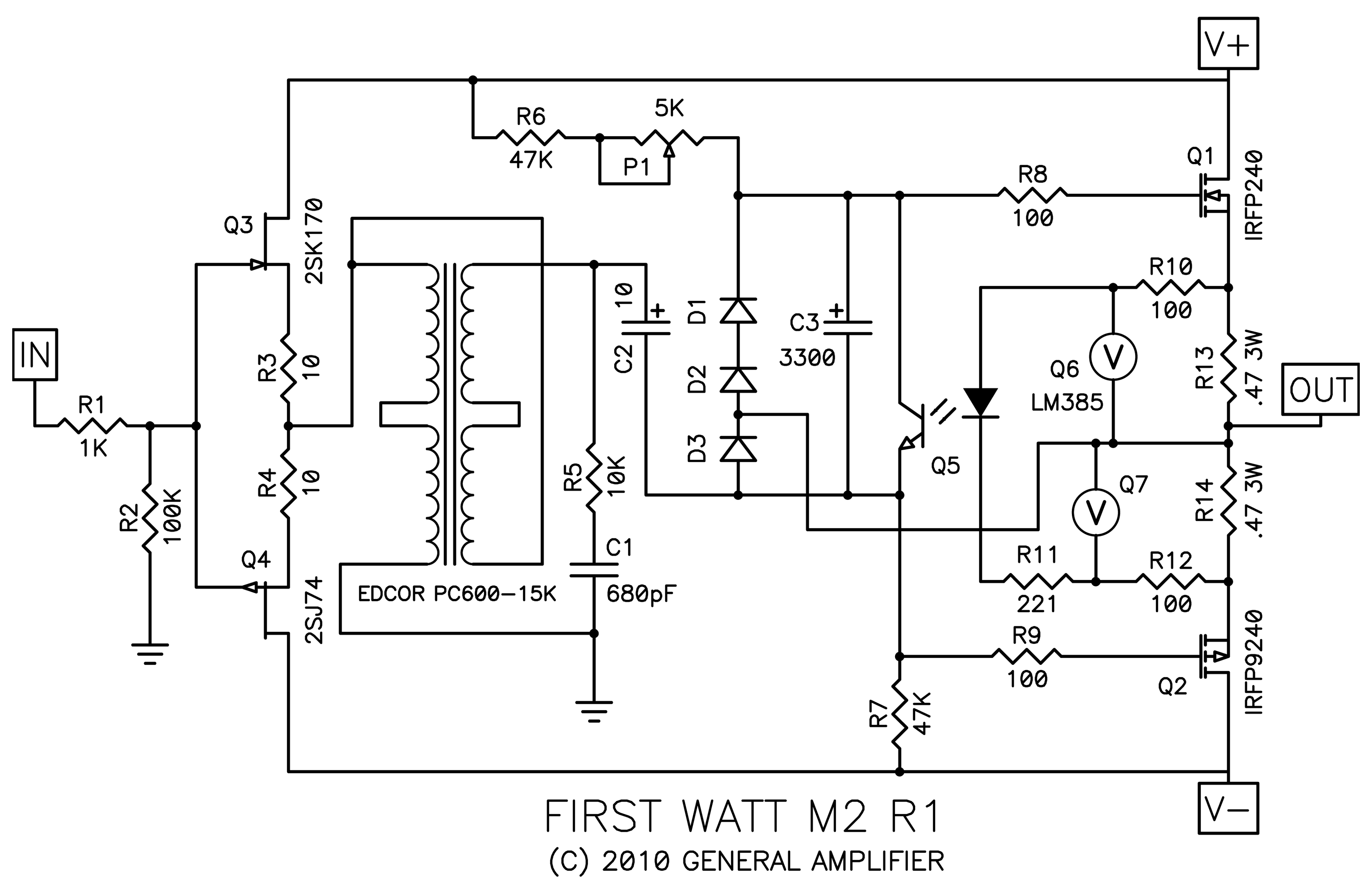
The full or local you can see on the schematic, local it is connected to the gates of the irfp240 and full it is connected to the sources of the irfp240 where also the speakers reside. it is easely seen on schematic.
I have some bags of ceramic spacing pads from china, these are 1 mm thick and full ceramic, do work oke and are less prone to chorts. And she cool a lot better then silicone because I test them on my hybride amp and on one channel with silicone the mosfet is much hotter then with ceramic pads, here I can put vinger on and is little hot,, and the other is to hot to put vinger on longer then 3 seconds. heat is cutt in half between them, good result.
regards
Attachments
... It's got to be thermal runaway.
...[/IMG]
That is no surprise. You don't have any compensation. I have build a circlotron a few years ago and I use a current source for compensation:
http://www.diyaudio.com/forums/soli...-circlotron-power-mosfets-11.html#post3070645
Q10 is mounted at the heatsink. D3 is necessary against overcompensation, so there is air to play.
D3 is an LED, and it controls the BD140 like a Vbe multiplier. I have never seen LED used as thermal sensor before.
D3 is not the sensor, Q10 is it. The LED is only voltage reference like zenerdiode. It restricts the effect of Q10.
Look at the construction:
http://xipix.de/elektro/zirclon140.html#A
Look at the construction:
http://xipix.de/elektro/zirclon140.html#A
Last edited:
Ok, the mounting with flying leads, that's similar to how I mounted a BD139 as Vbe multiplier on top of an IRF240 for my Quasi MOSFET amp. It's interesting how you are using the BD140 here with gate tied to collector - sort of like a temp controlled current source. So as the temp rises, resistance decreases and current goes up, like applying a short between upper rail and gate of Q12, thereby decreasing voltage differential seen by base of Q12?
The full or local you can see on the schematic, local it is connected to the gates of the irfp240 and full it is connected to the sources of the irfp240 where also the speakers reside. it is easely seen on schematic.
I have some bags of ceramic spacing pads from china, these are 1 mm thick and full ceramic, do work oke and are less prone to chorts. And she cool a lot better then silicone because I test them on my hybride amp and on one channel with silicone the mosfet is much hotter then with ceramic pads, here I can put vinger on and is little hot,, and the other is to hot to put vinger on longer then 3 seconds. heat is cutt in half between them, good result.
regards
I have been using silicone pads all this time and seems to work well as the softness allows it to fill in small gaps and imperfections in metal interface for best thermal contact - like thermal grease without the mess.
I just saw this great deal. Never need to buy these pads ever again.
https://www.amazon.com/gp/aw/d/B01B4VC7ZO/
I guess I made good progress following your tips. I now sit back and let you work out the temperature compensation and come back in again later. Getting first sound is huge accomplishment for me as I was worried I would never hear this amp sing 🙂
Last edited:
That is no surprise. You don't have any compensation. I have build a circlotron a few years ago and I use a current source for compensation:
http://www.diyaudio.com/forums/soli...-circlotron-power-mosfets-11.html#post3070645
Q10 is mounted at the heatsink. D3 is necessary against overcompensation, so there is air to play.
Hi Welcome here Moschfet.
My idea was a NTC resistor with a parallell resistor for compensation, I have now try a darlington in diode mode and this overcompensate (not at sim 🙁), so at cold start the current is in amps region, the NTc can do fine, needed in the lower section, for what X concerns he want class a and 1.3 amps idle, so mounting the ntc on the mosfet give a quick respons, your idea however is worth trying, a current source can be a splendid compensator, did not now it can act as a Vbe multiplier also, we need here experimentation, I did try with the darlington, it do work, but for x when need in class a we have to put temp sensor on the irfp itself, for class AB it go run at first but stabilizes later.
Using a fet as a sensor I can also try.
Last photo is without compensation and as you see a runaway, the other is with a darlington transistor who seems to sim oke, but it is not in real, Vbe multiplyer is just trial and error.
Thanks for the tips Moschfet
Attachments


Kees,
I am not opposed to running class AB if it sounds good. For some reason I could hear more distortion even at 250mA bias. Normally only 100mA would sound good. I took it to 1.3A just to see if it sounded better. It helped but I am not sure why it was needed. The Circlotron should work in class AB as you said it should. I would prefer. Or to have to mount the BJT directly on IRFP body as I like to solder the pins so body is very close
To OCB - this keeps the 4 screws and insulator washers on drivers captive so I don't have to Fritz with it each time the board comes on or off the heatsink. So a heatsink mounted compensator would be preferable.
What about something like how Pass M2 uses opto-coupled to sense current passing through source resistors for current feedback via optically coupled photo-transistor as Vbe multiplier. It doesn't require temp sensing as it limits current directly. Very reliable and rock steady.
Last edited:
X
You can put it in class a if you want, is your choise, your free to do that, I try to get it right for both, but in class A the sensor needs very close to irfp mosfets because of sensing quickly otherwise it is defective before the heatsink is warmed up.
I have tryed the darlington, it overcompensates, I had already put it in diode mode because the bottom side of the driver do regulate quite oke.
The pass amp is not a circlotron, so this do not work, and need a other way to do it like double version, and it is in signal path, as a bipolair, we need other way.
It will be oke soon, I work on it, I did now the idle runout is a problem, however laterals in it will cure it also.
For the sound in class AB we need 350 milliamps, minimum because these mosfets are quite non liniair, that is why she are used in class a to cope with that,
I think I go use 500 milliamps, a good compromise.
regards
Last edited:
It's interesting that with my other amps IRFP only needs about 80mA to 150mA to be very linear. But 500mA is a good compromise and I wouldn't mind operating there as it certainly reduces heat output. I wish laterals would have same pinouts. Why do they have to mess with it because to put laterals in now requires crossing two pins. I prefer to use the hexFETS as their bass resoonse, IMO, is better. I will wait for you to sort out the thermal compensation issue. Hopefully it's as simple as a BJT in current diode mode. I wonder if a thermistor can be used where you originally intended the NTC?
Hi X
A thermistor or NTC can be used, maybe even better then a transistor, we need a negative action thermistor so it has to be a NTC, in paralell with a extra resistor to adjust the compensation.
I have now use a BD380 in diode mode, and it overcompensates, when I however put the current to 700 mA it runs like hell to destruction when it was on a normal supply, mine is limited, do I put it to 500 mA it do be stable and steps back to lower current, lower, and lower, not stable.
So or I have mosfets who are not oke, running from 600 mA to destruction happens in just 10 a 15 seconds, lower then 600 mA and it steps back, strange behavior, bu I have not the transistor in the mosfet house, and I think this HAS to be done and is the cause.
putting things in serie with the transistor like a led do not work because there is to much current, but maybe a resistor in paralell with the transistor do work or a low value one in series.
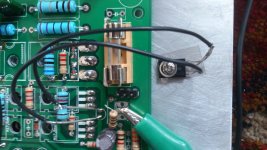
As on photo the irfp250N looks genuin.
regards.
A thermistor or NTC can be used, maybe even better then a transistor, we need a negative action thermistor so it has to be a NTC, in paralell with a extra resistor to adjust the compensation.
I have now use a BD380 in diode mode, and it overcompensates, when I however put the current to 700 mA it runs like hell to destruction when it was on a normal supply, mine is limited, do I put it to 500 mA it do be stable and steps back to lower current, lower, and lower, not stable.
So or I have mosfets who are not oke, running from 600 mA to destruction happens in just 10 a 15 seconds, lower then 600 mA and it steps back, strange behavior, bu I have not the transistor in the mosfet house, and I think this HAS to be done and is the cause.
putting things in serie with the transistor like a led do not work because there is to much current, but maybe a resistor in paralell with the transistor do work or a low value one in series.
As on photo the irfp250N looks genuin.
regards.
Attachments


Sad to say we will need to place a BJT in the sacred house of FETs. 🙂
It's a fine house but burns to the ground without a PN junction 😀
Those are definitely genuine IRFP's. The high quality epoxy on the body and exquisite satin finished pins (and probably back tab) are good indicators.
Do you have a suggested ohm range for the NTC thermistor? They come in 10k, 1k, 100R etc. should I get the lower circa value?
Sad to say we will need to place a BJT in the sacred house of FETs. 🙂
It's a fine house but burns to the ground without a PN junction 😀
Those are definitely genuine IRFP's. The high quality epoxy on the body and exquisite satin finished pins (and probably back tab) are good indicators.
Do you have a suggested ohm range for the NTC thermistor? They come in 10k, 1k, 100R etc. should I get the lower circa value?
I think the NTC need to be 50 ohms and a 10 ohm parallel, but a pot for the parallel resistor is a nice way to get in tune for the system, say 100 ohms.
Now I go test a mosfet in the lower section and see what it does.
I get stable now but when cold it has dan big idle current and a runout in some seconds but I have the sensor not on the irfp housing but some cm,s away, and I think this is very faulty. we have nice pcb but the under the pcb ppresent ifp have not much room above, maybe we need to do in future keep the power mosfets on side of board.
regards
I agree mounting MOSFETs on side - bent aiming out so that screws are visible makes easier mounting. You have placed all MOSFETs very tightly packed and I assume this was to get he same temperature for auto compensation. From cooling standpoint having more space would be better.
I agree mounting MOSFETs on side - bent aiming out so that screws are visible makes easier mounting. You have placed all MOSFETs very tightly packed and I assume this was to get he same temperature for auto compensation. From cooling standpoint having more space would be better.
That was yout idea X you did want a very small pcb, who I am succeed in, we go on for now what it will get to, otherwise the full balanced version come in play who pcb is also ready.
The runaway I have studied now, I thought the driver will be the cause but hee when I set idle on 600 mA it runs to amps in just some seconds🙁 normally the mosfet needs wamring up, if this happens so quickly there is a uge thermal resistance, I did count how fast it did, and it was 13 seconds for the supply limiter gets in, and was on 1.6 amps idle, the gate voltage from the driver and his setup for idle did nothing, it stays nicely on the same voltage, so the power mosfets itselfs did the runout, is it X not a little strange she runout in seconds, this means the mosfet core get hot very quick inside, and can say it is not very trustable.
When I set the idle on 500 mA the opposide happens, it runs back to very low levels while the gate voltage stays with 200 mV or so, somebody an idea here? because I do find this a very strange behavior.
I can remove them and test the irp240 ones.
Have some time this problem with other amp with bjt and this has also runout thermally but that are going very slow, X how much time it did spend before your fets did blow? I gess not is some seconds as you have listen to it on 1.4 amp idle, if I put that on mine, I have just 2 seconds or less😡 before things happen like on photo, who however did happen with your amp.
regards
kees
Attachments

Last edited:
- Home
- Amplifiers
- Solid State
- allFET circlotron