X
I have find out why you had half the voltage on the output, I have the same, and so I did going sim only the driver section and it seems that I have done wrong the feedback loops, need to be reversed because it has to be in opposite fase, now it is in fase making a dc amp, so the board do contain a fault.
you need feedback left to the right, so simpel a jumper do not work, except when make a new board, as you see how easy it is to oversee faults both did not see it, people here also not see it because in schema you see that it is fase fault connected.
regards
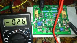
Did change the feedback to the proper fase, and yes now it works, I get the offset as low as 12 millivolts, it do run, but it runst between the adjusted value so it wlks up and down 12 millivolts, I see it cancels out automatically as mentioned.
Everything you change has effect, because of dc coupling devices, I see a current of 5 mA (tot 10 mA) for the input diff amps, do give the proper ilde adjustment reach for the power mosfets, th CCS stays, really needed for immunity of supply rippel voltages.
I have not all correntions and it do not oscillate, I get it not that far, so now testing with a signal generator how it does.
regard
Ok glad you are working out the bugs. Can left to right feedback be implemented with a jumper wire from the feedback header pins? It's not a high current trace error is it?
Good you have DC offset demonstrated at output. Do you have photos of the board?
Good you have DC offset demonstrated at output. Do you have photos of the board?
X
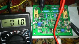
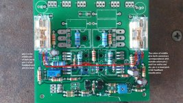
I have now a offset of 1/2.5 mv walking between this after 30 minutes of working, I have put a square wave in it, do also well. See pictures.
The feedback setting can indeed also be done with a connector, however, left go to right and vica versa. Have in eagle not corrected the board, as you see, small mistakes are easy made, but we are umans afcouse, the most strange animal on earth.
You have to couple the mosfets Q13 and Q14 plus Q1 and Q2 to each other, because I test with vinger, and then it go running with offset, nicely the zvn go opposite of 2sk170, so that is a very nice way to stabilize.
Square wave is 2 Khz from scope, giving 15 volts, this means 30 volts total with 1.2 V input, and this is as simulating did offer.
Attachments


Last edited:
After some time now, the heatsink is nice warm from the driver transistors and the offset stays between plus and minus 10mV, tighten the transistors so she feel each other make things even more stable.
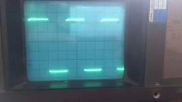
nice, we get somewhere, ooo yes the square in post 404 has on top some bend, this is because there is no ccs, and so earthed Q2 do have cause it.
See on scope when not use a ccs, the other grounded mosfet then do faseshift with low voltage and low impedance for unbalanced working giviing this strange square.. Other side is perfect and much higher voltage, ruining feedback.
Attachments

Last edited:
Can you show a schematic diagram with new feedback connections (actually red lines to current would be helpful. Where to where connect?)
Do you mean thermally couple the ZVNs and SK170's?
Do you mean thermally couple the ZVNs and SK170's?
Can you show a schematic diagram with new feedback connections (actually red lines to current would be helpful. Where to where connect?)
Do you mean thermally couple the ZVNs and SK170's?
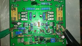
The way you did couple them was oke with yellow scrink sockets.
X the colors on the pcb you need top follow so red to red and other color the same.
Attachments
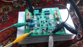
Have change R7 and R25 back to 100 ohms, maybe need even some higher to get good respons, change from 47 to 100 ohms did make sqaure a lot better (10Khz), has possible to do with resistor in stead of ccs, later when received them I test again, 100 ohms looks the best, also in sim, less modulation of the CCS under it.
And have not yet blow things, except two capacitors, one was landed in my nose because I did reverse the supply by mistake, no transistors damaged or broken
but maybe this because I have limit supply to 150 milliamps..
Voltage on scoop is 11 volts this means x 2 it is 22 volts output with 30 volt supply driver idel current total 60 mA is 30 mA each half of driver section.
I have measure these signals on gate input of both irfp250N mosfets, so menas when I put them in I have sound.
Attachments
Last edited:
Great progress Kees. You are close to first sound. What supply voltage will you be using for output stage?
Great progress Kees. You are close to first sound. What supply voltage will you be using for output stage?
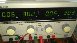
I have upstears a transformer with I think 2 x 35 volts, but driver stage need also higher voltages if you want use high voltages on circlotron itselfs voltages, I do still wait for parts, like rectifiers and capacitors 10.000 uf.
30 volts I do use now for driver, U can use also this voltage if you have that and 25 volts on circlotron, then the circlotron will clipp before driver stage does, and this is nice.
As you see on scope post 409 it is quite fast, and no overshoots, I dod not yet using capacitors in it, so completely capacitorless except supply lines.
regards
Last edited:
Yes, that squarewave looks exceptionally clean. Will adding caps make it more rounded? Why have you left laps off to now?
I just burned out IRF610/9610 on my Pass F5 headamp by plugging in DAC while amp was powered up. I wonder if that may have happened on my Circlotron? Those gates should get same 12v Zener and 1N4148 protection diodes like the main outputs perhaps?
I just burned out IRF610/9610 on my Pass F5 headamp by plugging in DAC while amp was powered up. I wonder if that may have happened on my Circlotron? Those gates should get same 12v Zener and 1N4148 protection diodes like the main outputs perhaps?
Yes, that squarewave looks exceptionally clean. Will adding caps make it more rounded? Why have you left laps off to now?
I just burned out IRF610/9610 on my Pass F5 headamp by plugging in DAC while amp was powered up. I wonder if that may have happened on my Circlotron? Those gates should get same 12v Zener and 1N4148 protection diodes like the main outputs perhaps?
let me see the schematic of that amp, then I can say it, for the circlotron the irfp610 9610 do only drive and are in serie with 120 ohm resistors so things get limited.
Did give that dac maybe a high peak or so, or was it only the 50 hz while put it on input?, never do when a amp is on, or connect a signal plug
because input is floating, if the gates of the irfp you burnt are on these inputs, she burn out because of this.
I have not yet received the caps, so I do now without them for now, still amp is very stable. it is used for remove ringing of overshoots and limiting bandwith to get HF out. Seems that it do not ring, this is good news, ringing can make amp sound bad.
If your headphone amp has drain followers then you not need gate protection diodes, and when it is source follower it does sometimes, but yours is headphone amp so output level is low, much lower then the 20 volts needed to distroy gate.
regards
regards
Last edited:
Here is the head amp I burned out the IRF610/9610 on. Immediately after I inserted DAC, I heard a loud click/pop on headphones (connected) then sound was anemic and distorted and clipped/raspy sounding. Replaced the input JFETs and problem still there.
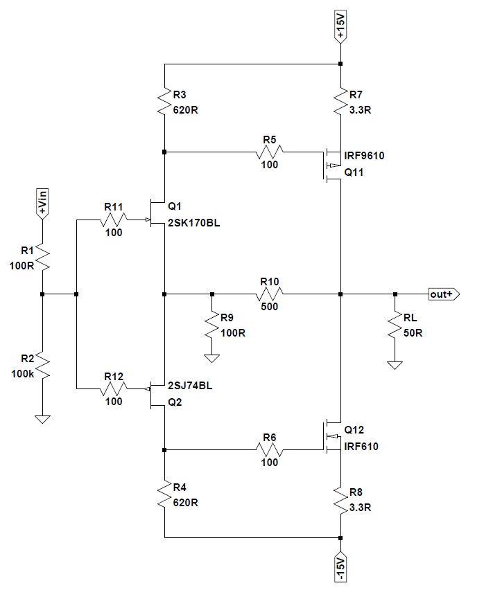
I am not using the R2 100k to GND on input and missing the R1 100R that feeds to the two 100R on the JFET gates. Input is directly coupled to split on 100R's. Also, I am using 2.2R for R7 & R8.
The power supply is regulated with 7815/7915 so is 15v or less. So maybe gate protection diodes not needed as less than 20v.
When this amp works it is very good - super clear low distortion and very neutral.
I see you have no cap on input, normally not needed but it is a big problem if driver dac have voltage on end, maybe there also something broken.
I have last week trouble sleeping and so I did measure again the big wifi mast above my head, has quite stroung signals, vakanty is over so it is active again and I feel that right away in the form of burning sensations and neelde feeling on skin, ear noise very loud.
And yes in holland we protect the companyes not the people.
googke spectran HF-60105 and look at the price, not a dull I think what people here do say about the meter.
regards
Attachments
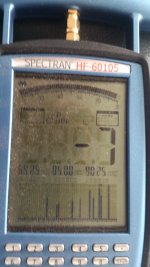
What does -7dBm reading mean? What are safe levels of RF? Is it the 2.4GHz frequency for WiFi? 2.4GHz is close to the water microwave bands for a reason - no one wants to use that for long haul comm because water can absorb it. If frequency is off or it tunes or autoscans, the inadvertent leakage onto absorption bands can be bad as that can be felt as warm tingling sensations of being in a microwave oven.
-7 is 200 mWs sometimes it jumps to +3 dBM and that is 1.5 watts or around. it is the 5.8 gigahertz band I measure, I did measuring from 4 gig to 9.5 gig
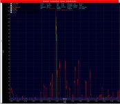
This is the magnetron when on with door close, on 4 meter distance, going to 92 Volts per meter and that is 22.9 watts on 8.6 gigahertz, this is quite high and a harmonic of the mircowave or even a radar transmitter pointed on me do not look healthy, possible nabure did open door block switch and turn microwave with opening to wall, and on the other side is my kitchen who is also nabure kitchen, these people need to be put away. Nabure woman has already a brain bloodclot in head, and very lucky, but this can happen when do such things, and she are young people. However the big transmitter signals are now dissapairs for 7 months now, but there is still enough radiation to disturb my sleep..
I have send to the police again, because past week she are been warned, if going on she go out og the house under force.
regards
Attachments
You are saying your crazy neighbor opens the microwave oven door and aims it at you through her wall!? The high levels you get seem consistent with that.
Why are there crazy people like that in this world? Sorry to hear of your troubles but if there is some way you can document or have proof of this abuse? I know in the US, intentional assault with a harmful RF source is quite serious. It's like physical assault with fistacuffs or knife. Even the abuse of RF spectrum is dealt with quickly because it affects commerce and air traffic safety.
Why are there crazy people like that in this world? Sorry to hear of your troubles but if there is some way you can document or have proof of this abuse? I know in the US, intentional assault with a harmful RF source is quite serious. It's like physical assault with fistacuffs or knife. Even the abuse of RF spectrum is dealt with quickly because it affects commerce and air traffic safety.
Last edited:
Yes thet is what i saying, because 92 volts leakage through a wall is quite possible, unfortanely, here in holland nobody can do something about it.
Maybe I have to emigrate to us then, serach me a nice wife there, I have no wife and like coloured woman, but that is there a issieu who she do not like in your country.
I did have the idea to ask asylum in australia, I like the Hi Mate term haha.
The proof is now send to the police.
Be tge way on the other side of my street the residential has rent a house to a couple who also do treat people, my street is a dumplace for tokkies as we call them,
these quite new nabure has already hunt 2 families out of there house, the new familie do live there just 5 months and the woman si so afread she will not sleep there anymore.
In neherlands we put people who do make much trouble in small villages like here, but hee, I am put here by judge, because hospital say I amd electro sensitive, and the residental
give that crazy nabure a permit to put a strong antenna on roof, with 3 years old childeren, this is so sick.
Happy that usa do care for citizens better then here.
and now back ontopic because the amp is promissing.
Last edited:
For DC protection of the circlotron these relay are very nice, the 2 x on/on version is one needed for each channel, so speaker is compleet disconnected from output.
JQX-12F 2Z DC 12V 30A DPDT General Purpose Power Relay 8 Pin AD | eBay
regards
JQX-12F 2Z DC 12V 30A DPDT General Purpose Power Relay 8 Pin AD | eBay
regards
That's a good price on that relay. I guess this amp really needs a DC and short circuit auto protect circuit too. Do you have a simple one to recommend? I have seen several designs in other threads. So many to choose from - just needs to be reliable and simple.
- Home
- Amplifiers
- Solid State
- allFET circlotron